-14-
Model G0458Z (Mfd. Since 7/19)
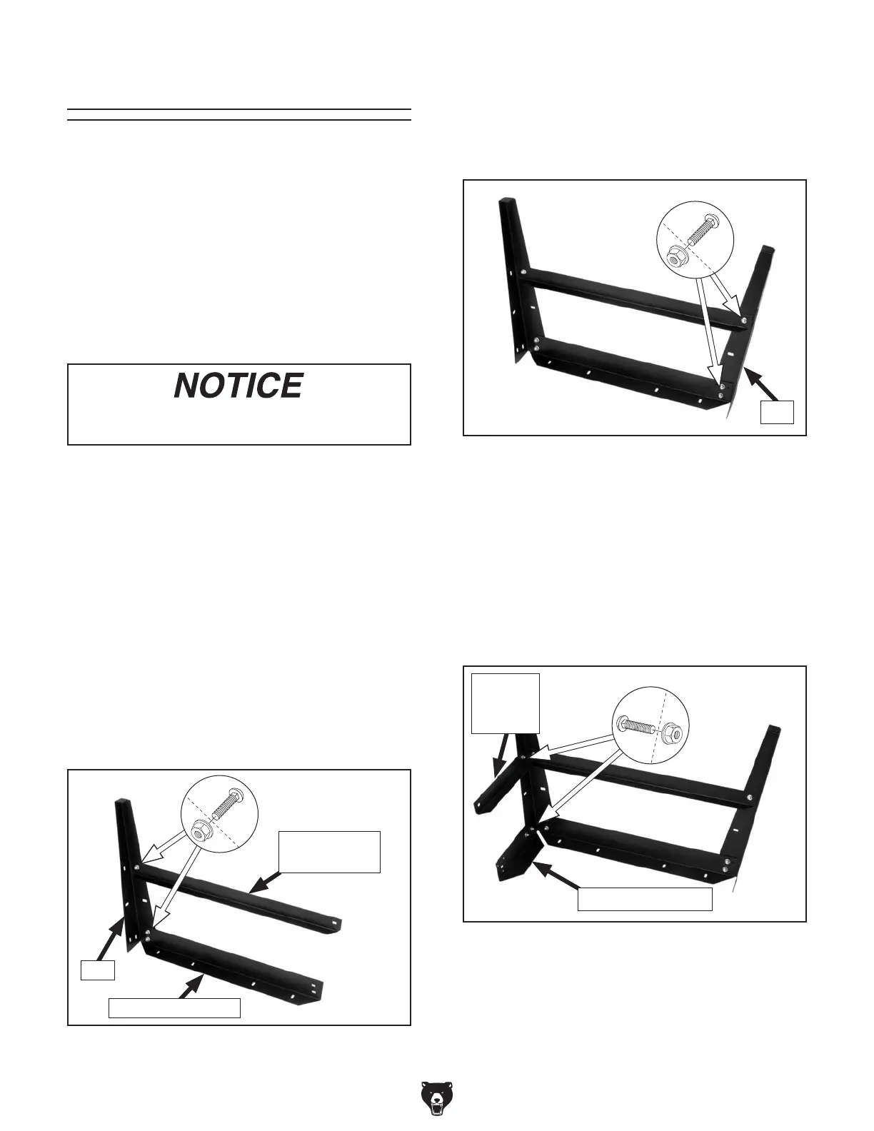
6. Mount top short bracket to stand leg assem-
bly with (2) M8-1.25 x 15 carriage bolts and
(2) M8-1.25 flange nuts, as shown in Figure
6.
7.
Mount bottom short bracket to stand leg
assembly with (1) M8-1.25 x 15 carriage
bolt and (1) M8-1.25 flange nut, as shown in
Figure 6.
4.
Secure a second leg to top and bottom long
brackets, as shown in Figure 5.
5.
Repeat Steps 2–4 with remaining compo-
nents to build remaining stand leg assembly.
Note: We recommend assembling the stand
upside down. To make it easier, have an assistant
hold the pieces while you assemble the stand.
To assemble sander:
1.
Move sander crate to an appropriate location,
as described in Site Considerations on pre-
vious page.
2.
Mount a top long bracket to a stand leg and
secure by hand with (2) M8-1.25 x 15 carriage
bolts and (2) M8-1.25 flange nuts, as shown
in Figure 4.
3.
Mount a bottom long bracket to stand leg and
secure by hand with (1) M8-1.25 x 15 carriage
bolt and (1) M8-1.25 flange nut, as shown in
Figure 4.
DO NOT final-tighten stand bolts until
stand components have been assembled.
Figure 6. Top and bottom short brackets
secured to stand leg assembly.
Bottom
Short
Bracket
Top Short Bracket
Figure 5. A completed stand leg assembly.
Leg
The machine must be fully assembled before it
can be operated. Before beginning the assembly
process, refer to
Needed for Setup and gather
listed items. To ensure the assembly process
goes smoothly, first clean any
parts that are cov-
ered or coated in heavy-duty rust preventative (if
applicable).
Assembly
Figure 4. Top and bottom long brackets secured
to a stand leg.
Top Long Bracket
Leg
Bottom Long
Bracket

 Loading...