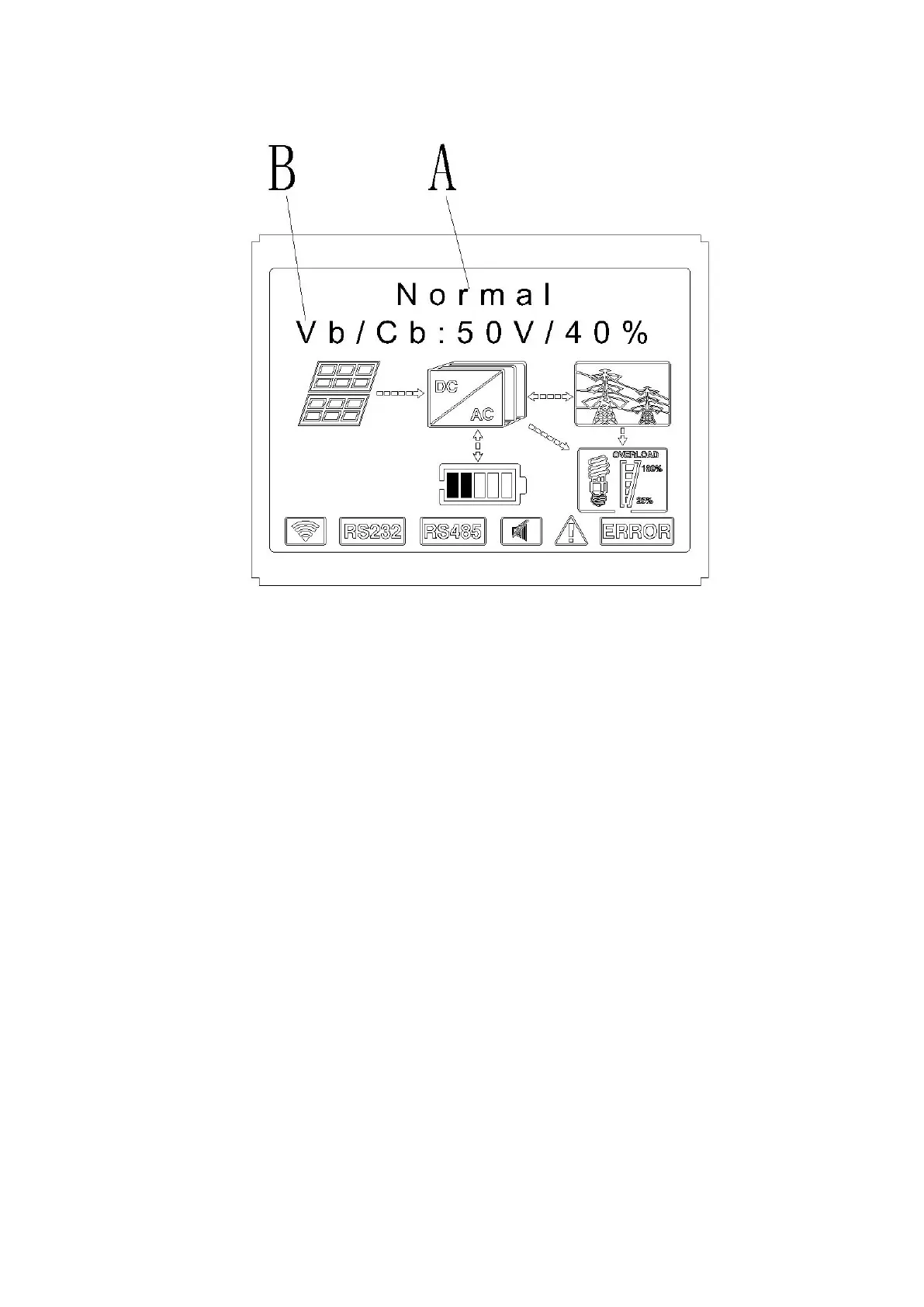
EasyManuals Logo

Growatt SPH5000 Installation Manual

Growatt SPH5000
66 pages
To Next Page IconTo Next Page
To Previous Page IconTo Previous Page
Page #47 background imageLoading...
Page #47 background image
Chart 6.4
The A line’s concluding information as follow:
1. Standby state: SPH is in standby state. No error in this state, but for other reasons, make it in a wait
state.
2. Normal state: SPH is normal working state.
3. Checking state: SPH is in self-check state, if there is no error or warning, SPH will go to normal state or
standby state. Otherwise it will go to fault state.
4. Programming state: SPH is in updating firmware state.
5. Fault state: SPH has fault information, it will be in stopped operational protection state.
The B line’s information as follow:
In normal, it will turn on page automatically, when pushing the button “UP”, the order of the paging
information as follow:

Other manuals for Growatt SPH5000

Questions and Answers:

Question and Answer IconNeed help?

Do you have a question about the Growatt SPH5000 and is the answer not in the manual?

Growatt SPH5000 Specifications

General IconGeneral
ModelSPH5000
TypeHybrid Inverter
Rated Power5000 W
Max. DC Voltage550 V
Max. Output Current22 A
Weight25 kg
Max. DC Power6000 W
Start Voltage150 V
Nominal DC Voltage360 V
Number of MPP Trackers2
AC Nominal Power5000 W
Max. AC Apparent Power5000 VA
AC Nominal Voltage230 V
AC Voltage Range180-280V
Nominal Grid Frequency50/60Hz
Total Harmonic Distortion (THDi)<3%
Power Factor Adjustment Range0.8 leading to 0.8 lagging
DC Injection Current<0.5% In
Switching Time<10 ms
Max. Charge/Discharge Power5000 W
Max. Charge/Discharge Current100 A
Protection degreeIP65
Max. PV Input Voltage550 V
Cooling MethodNatural Convection
Communication with BMSCAN
Operating Temperature Range-25°C to 60°C
MPPT Voltage Range120 V - 550 V

Related product manuals