5.2.5 Connection terminals for inputs and outputs
DANGER
Electric shock
Death or serious personal injury
‐ Make sure that the wires to be connected to the connection groups below are separated from
each other by reinforced insulation in their entire lengths.
3
15
8
26
23
25
24
7
B
Y
6
5
2
4
10
A
AI2
GDS RX
GDS TX
GND
GENIbus A
GENIbus B
+5 V
+24 V
+24 V
GND
GENIbus Y
GND
+5 V
DI1
AI1
DI3/OC1
+24 V*
+
+
+24 V*/5 V*
+24 V*
+5 V*
NC
C2
NO
NC
C1
NO
+24 V*
+
+
+24 V*/5 V*
+24 V*
+24 V*
OC
DI
GND
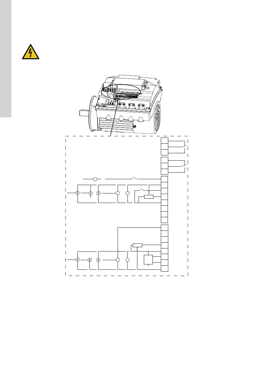
TM053510
Connection terminals, FM 200
* If you use an external supply source, there must be a connection to GND.
12
English (GB)