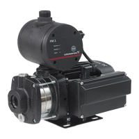
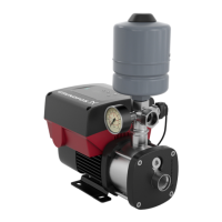
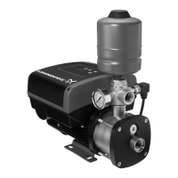
Connection terminals for inputs and outputs, FM 200. See the figure above.
Terminal Type Function
NC Normally closed contact
Signal relay 1 (LIVE or PELV)C1 Common
NO Normally open contact
NC Normally closed contact
Signal relay 2 (PELV only)C2 Common
NO Normally open contact
10 DI3/OC1
Digital input/output, configurable.
Open collector: Maximum 24 V resistive or inductive.
4 AI1
External sensor.
Pressure sensor: Pressure signal, 0.5 to 3.5
V. Connect the white wire to this terminal.
2 DI1
Digital input, configurable.
Digital input 1 is factory-set to be start or stop
input where an open circuit results in stop. A
jumper has been factory-fitted between
terminals 2 and 6. Remove the jumper if
digital input 1 is to be used as external start or
stop or any other external function.
5 +5 V Power supply to a potentiometer or sensor
6 GND Protective earth
A GENIbus, A GENIbus, A (+)
Y GENIbus, Y GENIbus, Y (GND)
B GENIbus, B GENIbus, B (-)
3 GND Protective earth
15 +24 V Power supply
8 +24 V Power supply
26 +5 V
Power supply to a potentiometer or sensor.
Pressure sensor: Voltage supply, +5 VDC,
PELV. Connect the brown wire to this terminal.
13
English (GB)
 Loading...


