17
English (US)
8.15 Motor protection
8.15.1 Single-phase motors
All CR pumps with single phase motors, except 10 hp, are
equipped with multi-voltage, squirrel cage induction motors which
include built-in thermal protection.
8.15.2 Three-phase motors
CR pumps with three-phase motors must be used with the proper
size and type of motor-protective circuit breaker to ensure the
motor is protected against damage from low voltage, phase
failure, current unbalance and overloads.
Use a properly sized circuit breaker with manual reset and
ambient-temperature compensated extra-quick trip in all three
phases. The overload protection should be set and adjusted to
the full-load current rating of the motor. Under no circumstances
should the overload protection be set to a higher value than the
full-load current shown on the motor nameplate. This will void the
warranty.
Set overload protection for auto transformers and resistance
starters in accordance with the recommendations of the
manufacturer.
Three-phase MLE motors (CRE-pumps) require only fuses as
circuit breaker. They do not require a motor-protective circuit
breaker. Check for phase unbalance (worksheet is provided.
See section 18. Worksheet for three-phase motors).
8.15.3 CRN-SF
The CRN-SF is typically operated in series with a feed pump.
Because the maximum allowable inlet pressure of the CRN-SF
increases from 73 psi (when pump is off and during start-up) to
365 psi (during operation), use a control device to start the CRN-
SF pump one second before the feed pump starts. Similarly, the
CRN-SF must stop one second after the feed pump stops.
See CRN-SF start-up timeline below.
Fig. 12 CRN-SF start-up
9. Commissioning
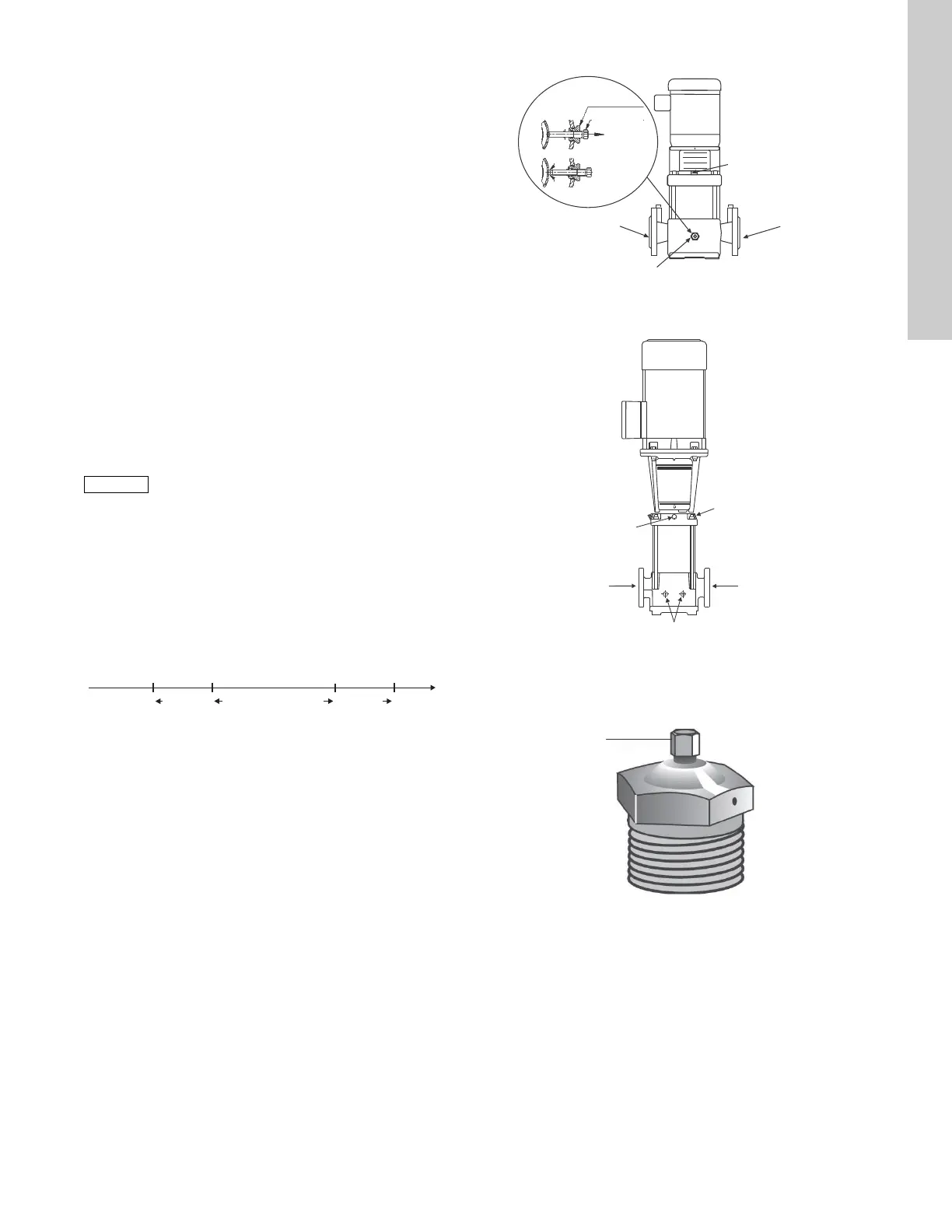
9.1 Priming
To prime the pump in a closed system or an open system where
the water source is above the pump, close the pump isolating
valve(s) and open the priming plug on the pump head.
See fig. 13, fig. 14, and fig. 15.
Fig. 13 Position of plugs and bypass valve
Fig. 14 Position of plugs CR, CRN 32, 45, 64, 90, 120, 150
Fig. 15 Vent plug
In open systems where the water level is below the pump inlet,
the suction pipe and pump must be filled with liquid and vented
before starting the pump.
1. Close the discharge isolating valve and remove the priming
plug.
2. Pour water through the priming hole until the suction pipe and
pump are completely filled with liquid. If the suction pipe does
not slope downwards away from the pump, the air must be
purged while priming the pump.
3. Replace the priming plug and tighten securely.
Standard allowable phase unbalance is 5 %.
TM04 3921 0409
TIME
CRN-SF
starts
CRN-SF
stops
Feed pump
starts
Feed pump
stops
1 or more
seconds
1 or more
seconds
Both pumps operating
TIME
CRN-SF
starts
Feed pump
starts
1 or more
seconds
Feed pump
stops
CRN-SF
stops
1 or more
seconds
Both pumps operating
TM04 3922 3613TM04 4036 3613TM04 3920 3613
Drain plug
Bypass
valve
Priming vent plug
CR(I)(N) 1s, 1, 3, 5,
10, 15, 20
CRT 2, 4, 8, 16
Suction
Drain plug
Discharge
Vent plug
Discharge
Priming plug
(Opposite side)
Suction
Drain plugs (G 1 1/2 A) with 1/4"
NPI gauge/sensor taps
Loosen
center plug
to vent
pump
Vent plug
 Loading...


