18
7.5 Menu OPERATION
When the communication between the R100 and the
pump has been established, "Contact with" appears
in the display. When the "arrow down" on the R100 is
pressed, menu OPERATION appears.
Note: The display "Contact with" appears only once,
i.e. when the R100 gets contact with the pump.
7.5.1 Setpoint
This display depends on the control mode selected
in the display "Control mode" in menu INSTALLA-
TION.
If the pump is forced-controlled via external signals,
the number of possible settings will be reduced, see
section 7.8 Priority of settings. Attempts to change
the settings will result in an indication in the display
saying that the pump is forced-controlled and
changes therefore cannot be made.
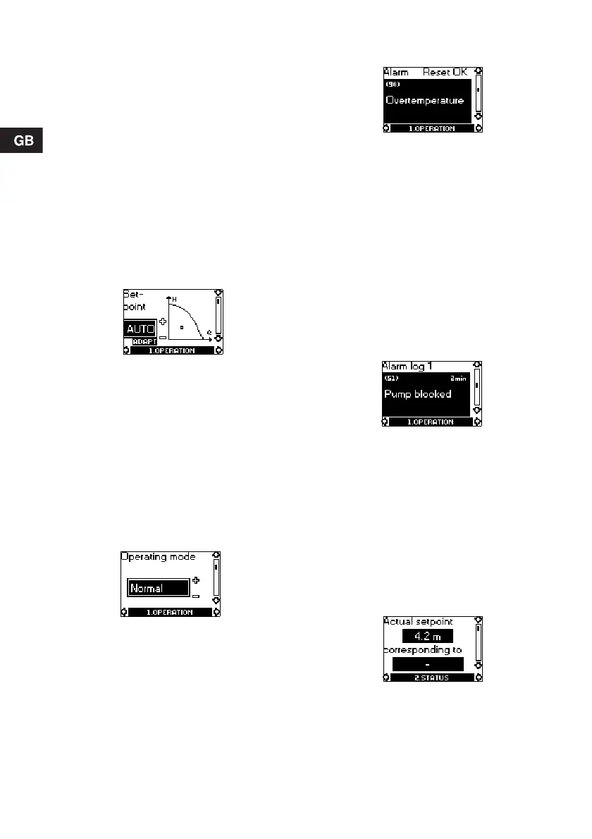
This display will appear when the pump is in
AUTO
ADAPT mode.
Set the desired setpoint by pressing the buttons "+"
and "–" on the R100 (not possible when the pump is
in AUTO
ADAPT mode).
Furthermore, it is possible to select one of these op-
erating modes:
• Stop
• Min. (min. curve)
• Max. (max. curve).
The display is different if proportional pressure, con-
stant pressure or constant curve has been selected.
The actual duty point of the pump is indicated by a
square in the Q/H field. No indication at low flow.
7.5.2 Operating mode
Select an operating mode:
• Stop
• Min. (min. curve)
• Normal (AUTO
ADAPT, proportional pressure, con-
stant pressure or constant curve)
• Max. (max. curve).
7.5.3 Fault indications
If the pump is faulty, the cause will appear in this dis-
play.
Possible causes:
• Pump blocked
• Internal fault
• Overvoltage
• Undervoltage
• Overtemperature
• Module fault
• Fault in module communication.
The fault indication can be reset in this display. If the
fault has not disappeared when resetting is at-
tempted, the fault indication will reappear in the dis-
play when communicating with the pump.
7.5.4 Alarm log
The alarm code with text appears in this display. The
display also shows the number of minutes the pump
has been connected to the electricity supply after the
fault occurred.
The last five fault indications will appear in the alarm
log.
7.6 Menu STATUS
The displays appearing in this menu are status dis-
plays only. It is not possible to change or set values.
The actual values in the display are stated as a
guide.
7.6.1 Actual setpoint
Field "Actual setpoint":
Actual setpoint of pump.
Field "corresponding to":
Actual setpoint in % of the setpoint set if the pump is
connected to an external analog 0-10 V signal trans-
mitter or if temperature influence or proportional-
pressure control is activated.

 Loading...