7
3. Installation
Arrows on the pump housing indicate the liquid flow
direction through the pump.
3.1 Changing the control box position
Procedure:
3.1.1 Control box position
For permissible control box positions, see the Quick
Guide.
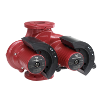
3.2 Twin-head pumps
Twin-head pumps are supplied fitted with a GENI
module on each control box. The modules are con-
nected via a cable. The modules determine the oper-
ating mode of the pump, see section 6.9.1 Control of
twin-head pumps.
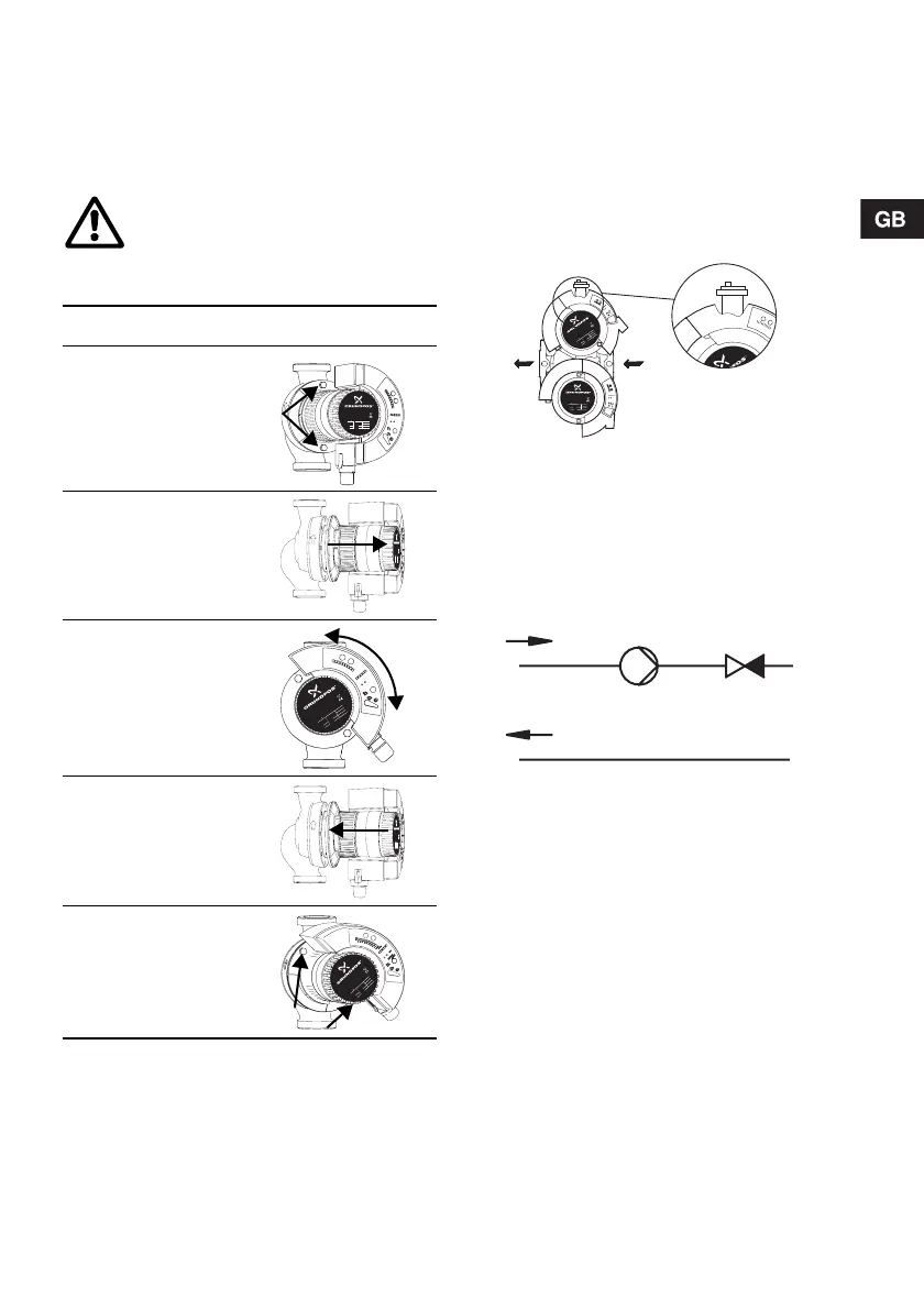
Note: Twin-head pumps mounted in horizontal pipes
must be fitted with an automatic air vent (Rp ¼) in
the upper part of the pump housing.
The automatic air vent is not supplied with the pump.
.
Fig. 1 Automatic air vent
3.3 Non-return valve
If a non-return valve is fitted in the pipe system, see
fig. 2, it must be ensured that the set minimum dis-
charge pressure of the pump is always higher than
the closing pressure of the valve. This is especially
important in proportional-pressure control mode
(reduced head at low flow).
Fig. 2 Non-return valve
3.4 Frost protection
If the pump is not used during periods of frost, nec-
essary steps must be taken to prevent frost bursts.
Before any dismantling of the pump, the
system must be drained or the isolating
valves on both sides of the pump must be
closed as the pumped liquid may be scald-
ing hot and under high pressure.
Step Action Illustration
1
Remove the two
screws.
TM03 0474 5204
2
Pull the stator and
the pump head ap-
prox. 5 mm out.
TM03 0475 5204
3
Turn the stator and
the pump head to
the desired posi-
tion.
TM03 0476 5204
4
Push the stator and
the pump head into
place.
TM03 0475 5204
5
Refit the two
screws.
TM03 0580 0305
M
A
X
9
8
6
7
5
4
3
2
1
m MIN
STOP
EXT
AUTO
ADAPT
P/N: 96281016
PC: 0512
Made in Germany
1 230-240V 50/60 Hz
I
1/1
(A)
P
1
(W)
TF 110
0,04 10 IP 44
0,80 184
B
Min.
Min.
Max.
Max.
MAGNA 32-100
Max.
10
Bar
M
AX
9
8
6
7
5
4
3
2
1
m
M
I
N
STOP
EXT
AUTO
ADAPT
P/N: 96281016
PC: 0512
Made in Germany
1 230-240V 50/60 Hz
I
1/1
(A)
P
1
(W)
TF 110
0,04 10 IP 44
0,80 184
B
Min.
Min.
Max.
Max.
MAGNA 32-100
Max.
10
Bar
M
A
X
9
8
6
7
5
4
3
2
1
m
M
IN
STOP
E
X
T
AUTO
A
D
A
P
T
P
/
N
:
9
6
2
8
1
0
1
6
P
C
:
0
5
1
2
M
a
d
e
in
G
e
r
m
a
n
y
1
2
3
0
-
2
4
0
V
5
0
/
6
0
H
z
I
1
/
1
(
A
)
P
1
(
W
)
T
F
1
1
0
0
,0
4
1
0
I
P
4
4
0
,8
0
1
8
4
B
M
i
n
.
M
i
n
.
M
a
x
.
M
a
x
.
M
A
G
N
A
3
2
-
1
0
0
M
a
x
.
1
0
B
a
r
M
A
X
9
8
6
7
5
4
3
2
1
m
M
IN
STOP
EXT
AUTO
ADAPT
P/N: 96281016
PC: 0512
Made in Germany
1 230-240V 50/60 Hz
I
1/1
(A)
P
1
(W)
TF 110
0,04 10 IP 44
0,80 184
B
Min.
Min.
Max.
Max.
MAGNA 32-100
Max.
10
Bar
P
/
N
: 96
2
8
1
0
1
6
P
C
: 0
5
1
2
M
a
d
e
i
n
G
e
r
m
a
n
y
1
2
3
0
-2
4
0
V
5
0
/6
0
H
z
I
1
/1
(A
)
P
1
(W
)
T
F
1
1
0
0
,0
4
1
0
IP
4
4
0
,8
0
1
8
4
B
M
in.
M
in.
M
ax
.
M
ax
.
MAGNA 32-100
M
ax
.
1
0
B
a
r
TM03 0377 5004TM02 0640 0301
P/N: 96281016
PC: 0512
M
a
d
e
i
n
G
e
r
m
a
n
y
1 230-240V 50/60 Hz
I
1/
1
(A)
P
1
(W)
TF 110
0,04 10
IP 44
0,80 184
B
M
i
n
.
M
i
n
.
M
a
x
.
M
a
x
.
M
A
G
N
A
3
2
-
1
0
0
M
a
x.
10
Ba
r
P
/
N
:
9
6
2
8
1
0
1
6
P
C
:
0
5
1
2
M
a
d
e
i
n
G
e
r
m
a
n
y
1
2
3
0
-
2
4
0
V
5
0
/
6
0
H
z
I
1
/
1
(
A
)
P
1
(
W
)
T
F
1
1
0
0
,
0
4
1
0
I
P
4
4
0
,
8
0
1
8
4
B
M
i
n
.
M
i
n
.
M
a
x
.
M
a
x
.
M
A
G
N
A
3
2
-
1
0
0
M
a
x
.
1
0
B
a
r

 Loading...