4. Installation
26 PNEG-2343 U-Trough Free Flow Unloading System
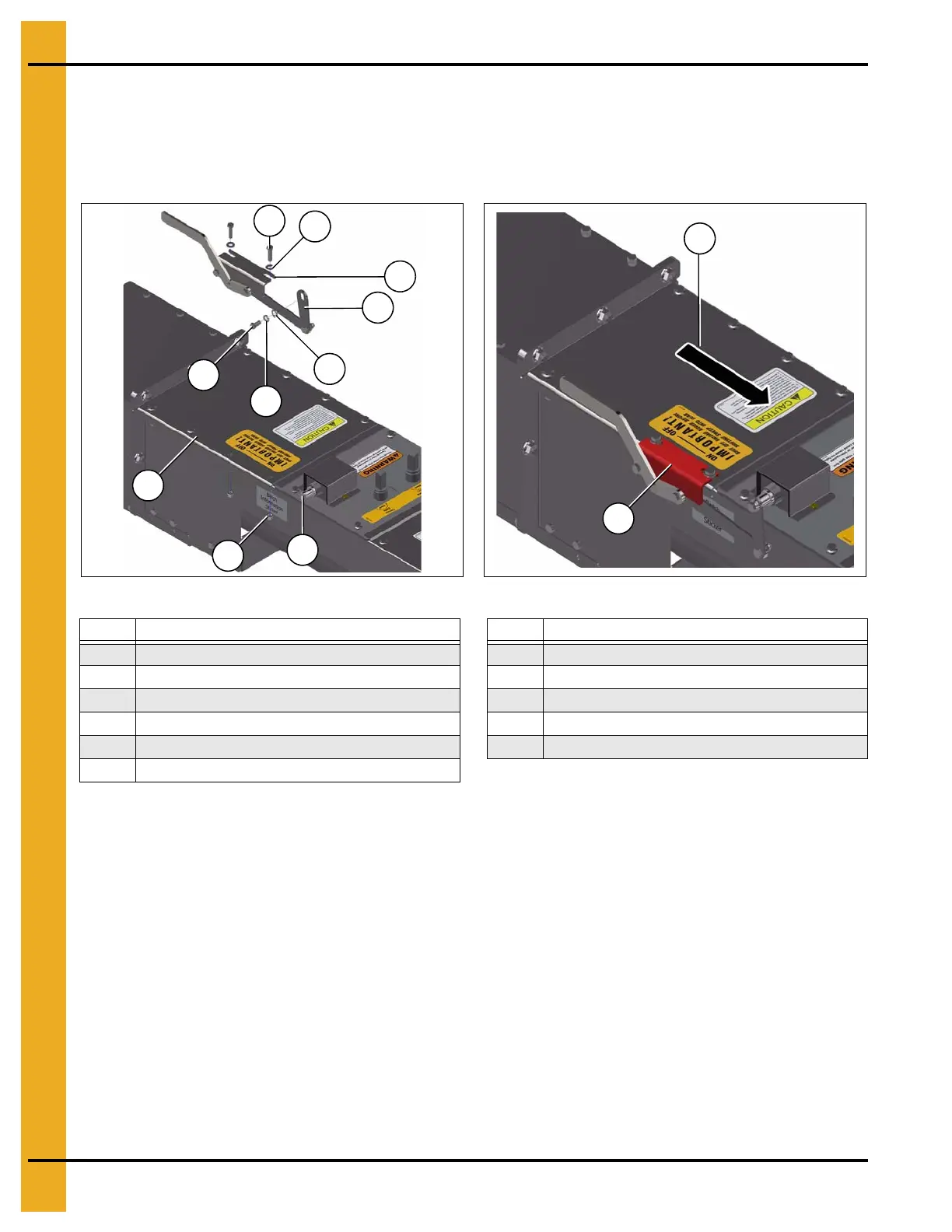
8. Install the shifter assembly at the powerhead end of the unloader. Secure the shifter linkage end (72)
to the shifter shaft (73) with the 3/8" x 3/4" bolt (6) and washers (26 and 30). Secure the shifter
bracket (74) to the lid (75) with the 3/8" x 1-1/4" bolts (4), nuts (17) and washers (26).
NOTE: If you also installing an inclined powerhead, skip to incline powerhead on Page 39 before
completing this step. (See Figure 4U and Figure 4V.)
Figure 4U
Figure 4V
Bracket Adjustment
The back-to-front location of the shifter assembly bracket MUST be adjusted to ensure proper shifting of
the gearbox.
Install the bracket with the handle in the down (OFF) position as shown and the bracket slid as far towards
the bin center as the slots will allow. Then test shifting (see Step 9). Adjust the bracket away from the bin
center as needed to get proper shifting.
9. To complete installation, ensure that the gearbox is shifting properly.
• First lock out the power supply if it has been hooked up.
• Shift the sweep into the OFF position and turn the unloader flight by hand.
NOTE: The sweep flight should not be turning.
• Shift the sweep into ON position and turn the unloader flight again by hand.
NOTE: The sweep flight should now turn, along with the unloader flight and the elevator wheel.
Ref # Description Ref # Description
4 3/8" x 1-1/4" Bolt Grade 5 UNC Plated (2) 71 Shifter Assembly Bracket
6 3/8" x 3/4" Bolt Grade 5 UNC (1)
72 Shifter Linkage End
17 3/8" Serrated Flange Nut (2) 73 Shifter Shaft
26 3/8" Flat Washer Plated (3)
74 Shifter Bracket
30 3/8" Lock Washer Plated (1) 75 Lid
70 Towards Bin Center