8. Dimensions
54 PNEG-2343 U-Trough Free Flow Unloading System
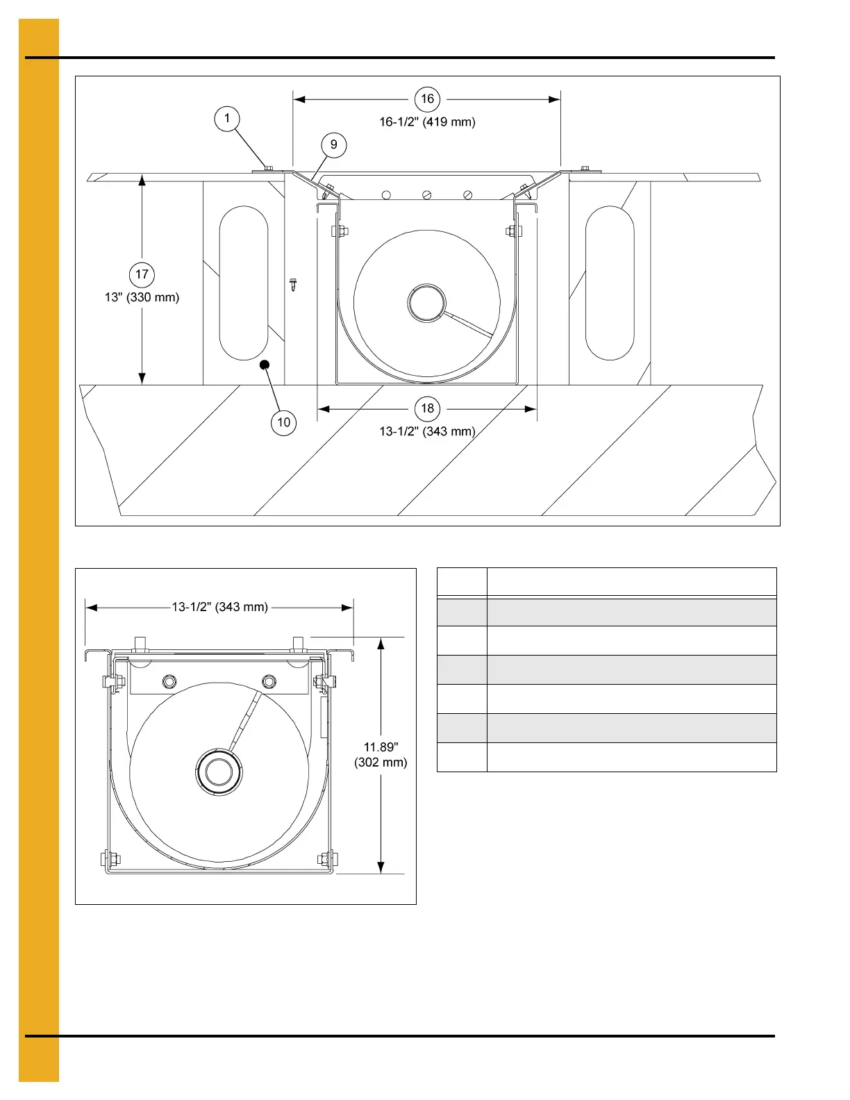
Figure 8F Unloader Section View Through Gate
Figure 8G Overall Unloader Dimensions Under Bin
IMPORTANT: It is imperative that the concrete be absolutely level where the unloader is to be positioned.
Failure to do so may cause distortion of the U-Trough when the unit is anchored down.
This distortion is likely to cause excessive operational noise from incorrect U-Trough
flight clearance.
Ref # Description
1 Self-Tapping Screw
9 Floor Flange Surface
10 Aeration Floor Support
16 Floor Flange Wdith
17 Typical Aeration Floor Height
18 Maximum Unloader Width