GPP Series User Manual
18
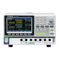
Channel number and distribution vary by
models with different colors identifications:
CH1: Yellow CH2: Blue CH3: Pink CH4:
Green CH1 is master and CH2 becomes yellow
under tracking series and tracking parallel
modes.
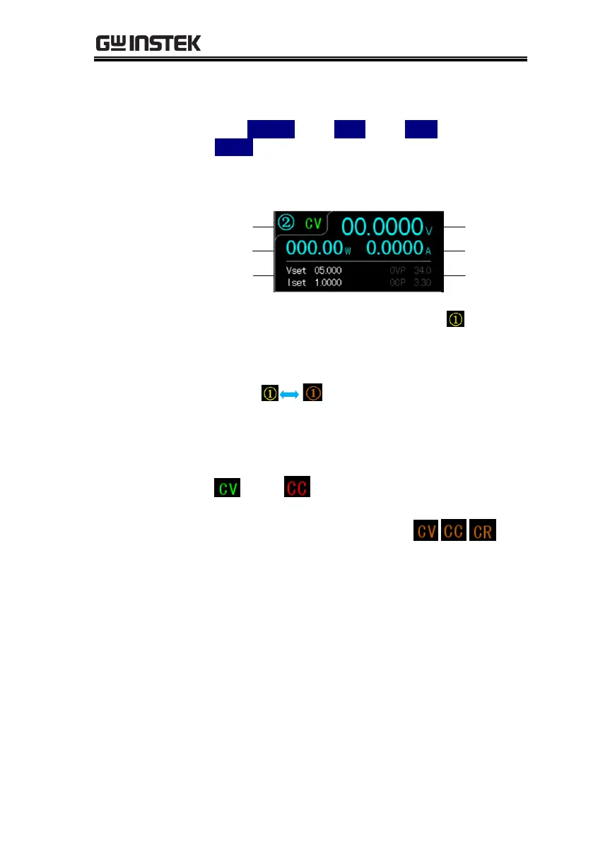
Channel/
Status
Power
display
V/I
setting
Voltage
display
Current
display
OVP/OCP
setting area
Color of channel remains the origanl when
not in the state of setting.
Color of channel blinks between the original and
orange when being set.
Display active channel state
Power supply: CH1/CH2/CH3/CH4: green
or red
Load Mode: CH1/CH2: orange
Displays the output voltage with up to 6 digits
of resolution. The default units are Volts (V).
 Loading...