3-2
When the depth of a switch is greater than 300 mm (11.8 in.), the front mounting ears only secure the
switch rather than bear its weight.
Introduction to mounting ear
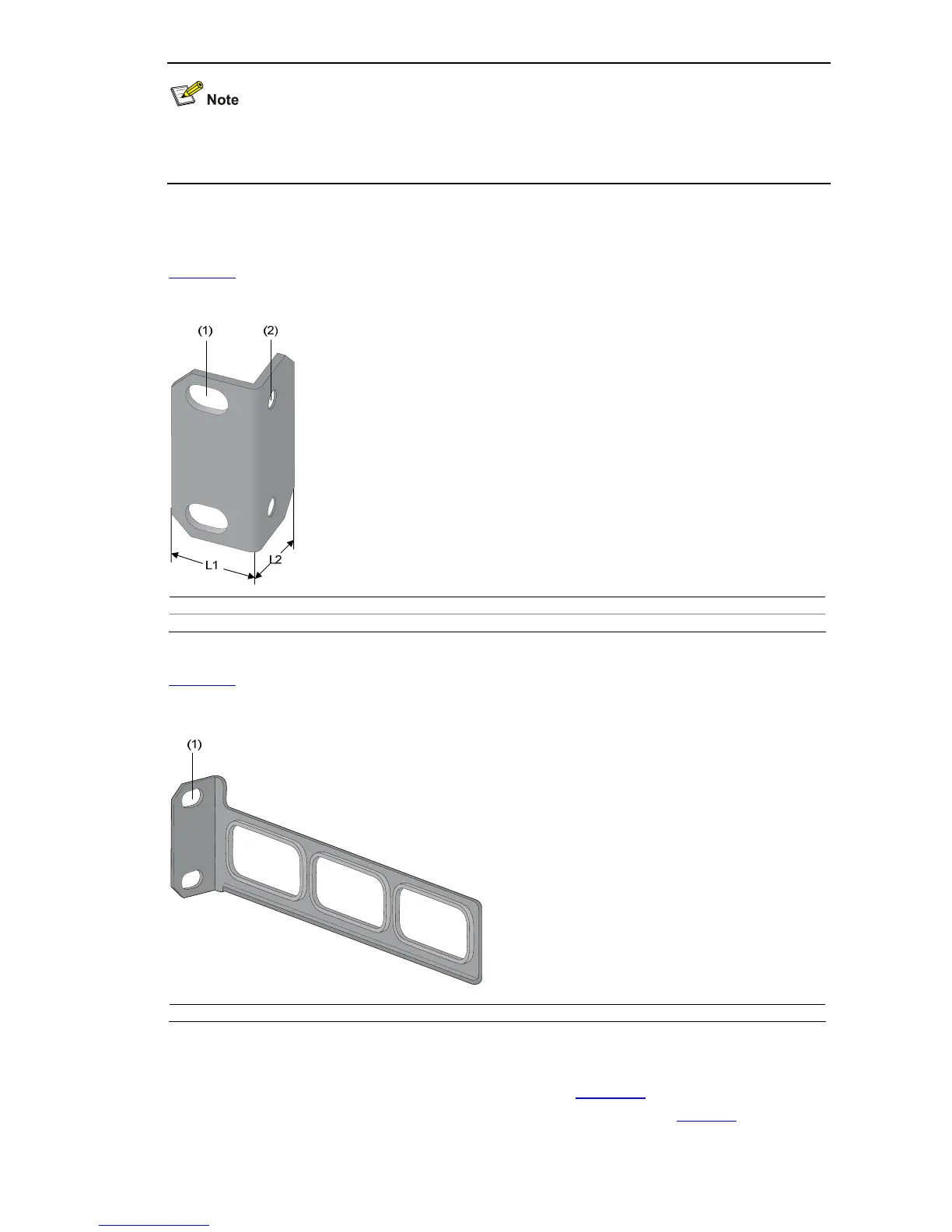
Figure 3-1 shows the appearance of a front mounting ear.
Figure 3-1 Appearance of a standard front mounting ear
(1) Screw hole used to fix the mounting ear to the cabinet (Use one M6 screw)
(2) Screw hole used to fix the switch to the mounting ear
Figure 3-2 shows the appearance of a rear mounting ear.
Figure 3-2 Appearance of a rear mounting ear
(1) Screw hole used to fix the mounting ear to the cabinet (Use one M6 screw)
When you install S3100 Series Ethernet Switches into 19-inch standard cabinets, you should select
front mounting ears with a proper length (L1 as shown in
Figure 3-1) according to the physical
dimensions of switches. For the selection of front and rear mounting ears, see
Table 3-3.

 Loading...


