4-2
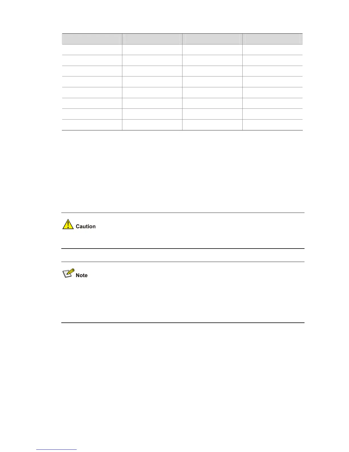
Table 4-1 Console cable connector pinouts and mapping relation
RJ-45 Signal Direction DB-9
1 RTS ← 7
2 DTR ← 4
3 TXD ← 3
4 CD → 1
5 GND — 5
6 RXD → 2
7 DSR → 6
8 CTS → 8
Connection Procedure
Follow these steps to connect a terminal device, a PC for example, to the switch:
Step 1: Connect the DB-9 female connector of the console cable to the serial port of the PC or the
terminal device used to configure the switch.
Step 2: Connect the RJ-45 connector of the console cable to the console port of the switch.
Identify the label of the port before connecting a connector.
When connecting a PC to a powered-on switch, you are recommended to connect the DB-9 connector
of the console cable to the PC before connecting the RJ-45 connector to the switch. When
disconnecting a PC from a powered-on switch, you are recommended to disconnect the DB-9
connector of the console cable from the PC after disconnecting the RJ-45 connector from the switch.
Setting Terminal Parameters
Step 1: Start the PC and run the terminal emulation program such as the Terminal of Windows 3.1 or the
HyperTerminal of Windows 95/98/NT/2000/XP.
Step 2: Set terminal parameters (take the HyperTerminal of Windows 2000 as an example).
Parameter requirements: Set bits per second to 9600, data bits to 8, parity check to none, stop bits to 1
and flow control to none. Select VT100 as terminal emulation. The following is the specific procedure:

 Loading...


