3-21
z Use cable ties to bind the two power cables to the protruding part at the back of the air filter, as
shown in
Figure 3-28.
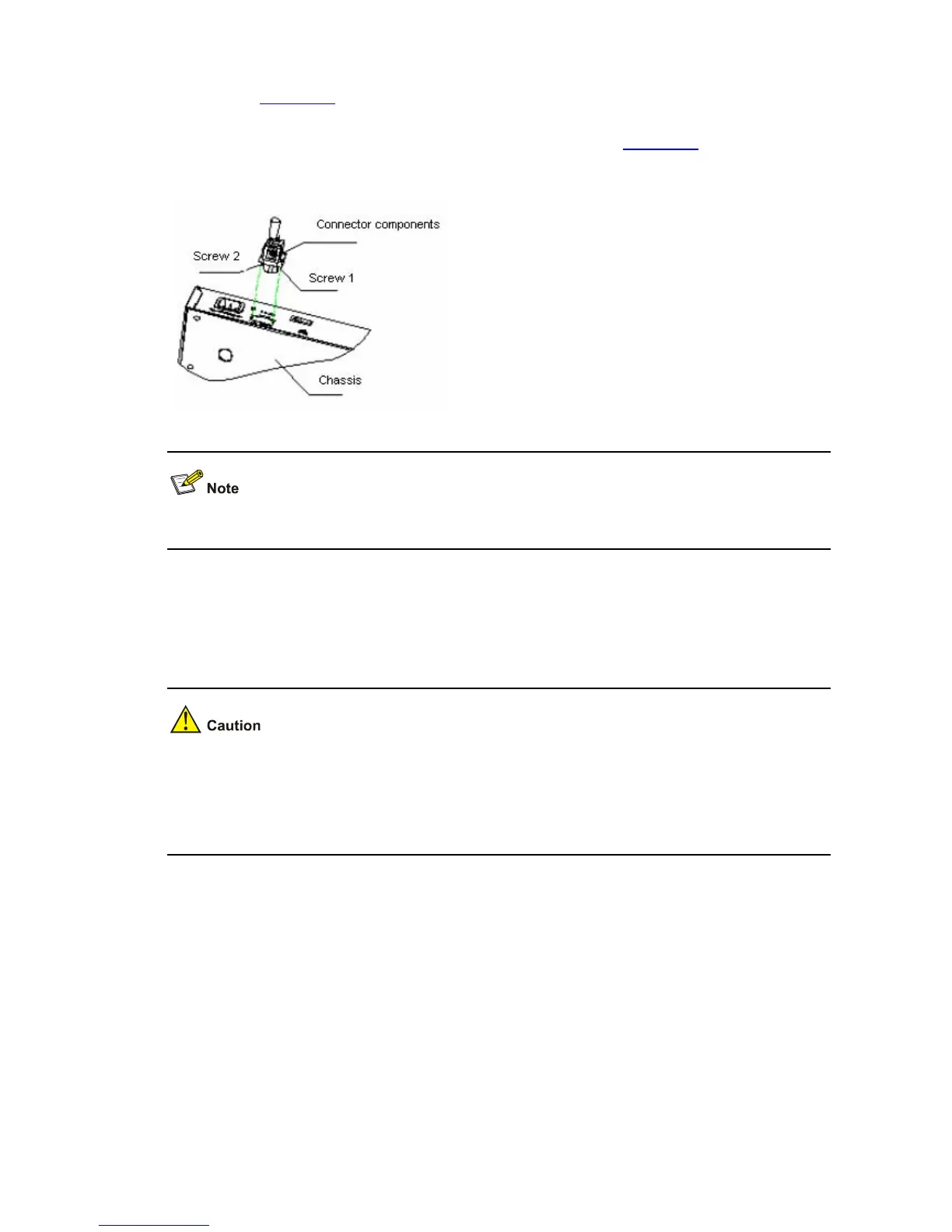
3) Insert the connector into the DC socket directly. Use the flat-blade screwdriver to fix the connector
with screw 1 and screw 2 (delivered with the switch), as shown in
Figure 3-29.
Figure 3-29 Fix the RPS DC power connector to the chassis
The location of the DC power socket varies with devices.
4) Connect the other end of the RPS DC power cord to the external RPS power supply system.
5) Check whether the PWR LED on the front panel of the switch is ON. If yes, the power is properly
connected.
z Before powering on the switch, you must properly connect the grounding cable.
z The DC power cable should be less than 3 meters long.
z Only the recommended RPS can be used for S3100-26TP-PWR-EI Ethernet switches. The –48
VDC in the equipment room cannot be used directly. Otherwise, the device may be damaged.
Installing an Expansion Interface Module
Installation procedure
Step 1: Wear an ESD-preventive wrist strap, ensure a good skin contact and make sure that the
ESD-preventive wrist strap is properly grounded.
Step 2: Loosen the mounting screws of the filler panel on the interface module slot of the switch's front
panel with a Phillips screwdriver and remove the filler panel.

 Loading...


