3-20
2) Use a flat-blade screwdriver to loosen the two screws on the DC input terminal blocks. Connect the
power ground return cable to the RTN(+) terminal and the power output cable to the NEG(-)
terminal. Tighten the two screws respectively to fix the power cables.
3) Check whether the PWR LED on the front panel of the switch is ON. If yes, the power is properly
connected.
z Before powering on the switch, you should properly connect the grounding cable.
z The DC power cable should be less than 3 meters long.
DC power cable connection for S3100-26TP-PWR-EI Ethernet switch
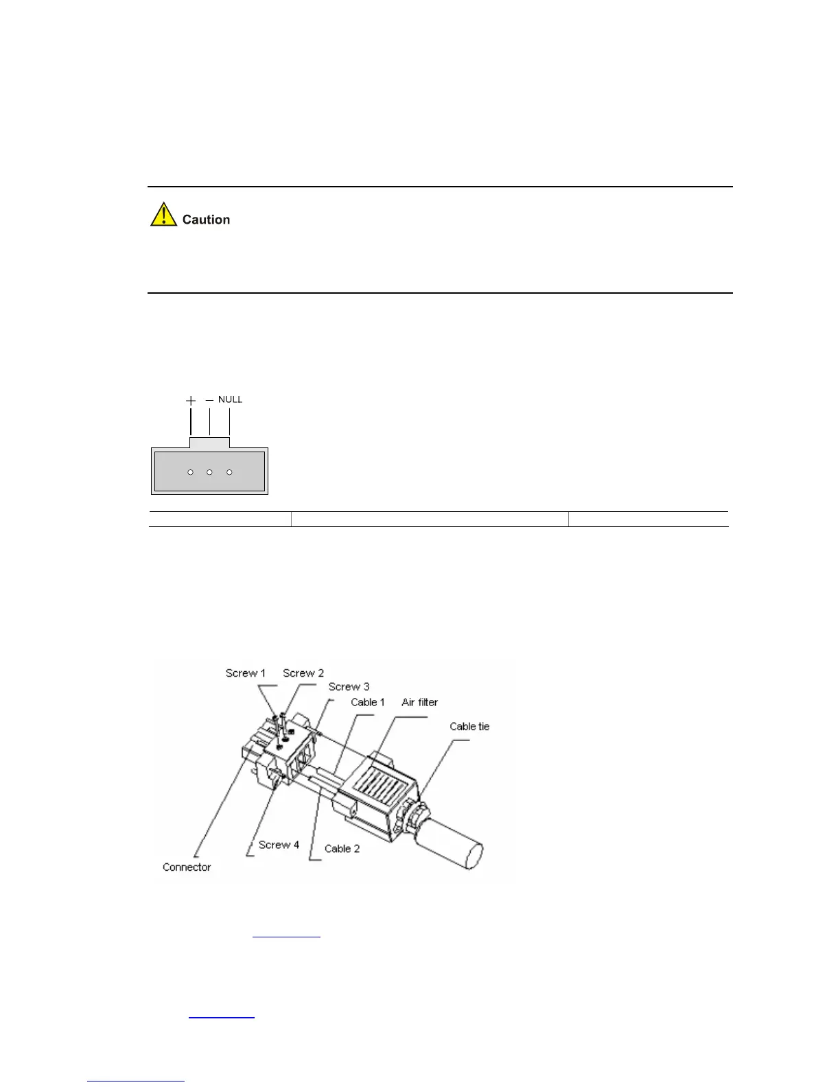
Figure 3-27 RPS DC power socket for S3100-26TP-PWR-EI Ethernet switch
+: Working ground –: Voltage input (–52 VDC to –56 VDC) NULL: Reserved
1) Connect one end of the grounding cable (delivered with the switch) to the grounding screw and the
other end to the ground nearby.
2) Assemble the DC power connector as follows:
Figure 3-28 RPS DC power connector
z As shown in Figure 3-28, pass the two power cables through the air filter, insert them into the
corresponding holes, and tighten them with screw 1 and screw 2. The positive and negative poles
of the power cables must correspond to the silkscreen above the holes.
z Use a flat-blade screwdriver to fix the air filter on the connector with screw 3 and screw 4, as shown
in
Figure 3-28.

 Loading...


