3-11
Introduction to screw and anchor kit
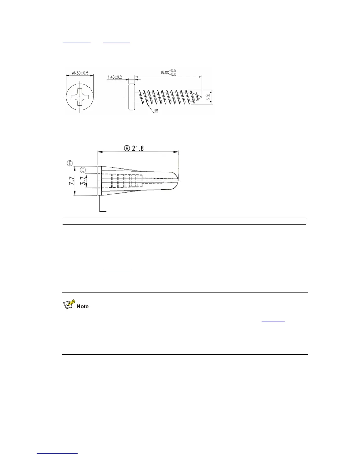
Figure 3-14 and Figure 3-15 show the recommended sizes (in mm) of screws and anchor kits used for
mounting:
Figure 3-14 Screw
Figure 3-15 Anchor kit
(1)(1)
(1) Outside edge of anchor kit
Installation procedure
The wall-mounting procedure is as follows:
1) As shown in
Figure 3-16, drill two holes 5 mm across in the wall on the same horizontal line, with a
distance of X mm.
z The distance X between holes varies with devices. For specific distances, see Table 3-4.
z Drill two holes according to the sizes of anchor kits and screws so that anchor kits could go into the
holes, only the edges could remain outside the wall, and the screws could be fixed on the wall
tightly.
2) Insert anchor kits into the holes and keep only the edges outside the wall.
3) Drive screws into the anchor kits, keeping the inside of screw head at least 1.5 mm (0.06 in.) away
from the edge of the anchor kit so that the switch could hang on the screws securely.

 Loading...


