28
Grounding the switch
CAUTION:
• Before using the switch, connect the grounding cable properly to guarantee lightning protection and
anti-interference of the switch.
• The power interface and grounding terminals in this section are for illustration only.
The power input end of the switch has a noise filter, whose central ground is directly connected to the
chassis to form the chassis ground. You must securely connect this chassis ground to the earth so that the
faradism and leakage electricity can be safely released to the earth to minimize EMI susceptibility of the
switch.
The S3100V2 Switch Series provides the grounding modes as shown in Table 8. S
elect an appropriate
grounding mode as required.
Table 8 S3100V2 Switch Series grounding modes
Switch model Grounding mode
S3100V2-26TP-SI
S3100V2-16TP-SI
S3100V2-8TP-SI
S3100V2-26TP-EI
S3100V2-16TP-EI
S3100V2-8TP-EI
S3100V2-8TP-PWR-EI
S3100V2-26TP-PWR-EI
S3100V2-16TP-PWR-EI
• Grounding the switch with a grounding strip
• Grounding the switch with a grounding conductor buried in the earth ground
• Grounding the switch with the PE wire of an AC power supply
Grounding cable
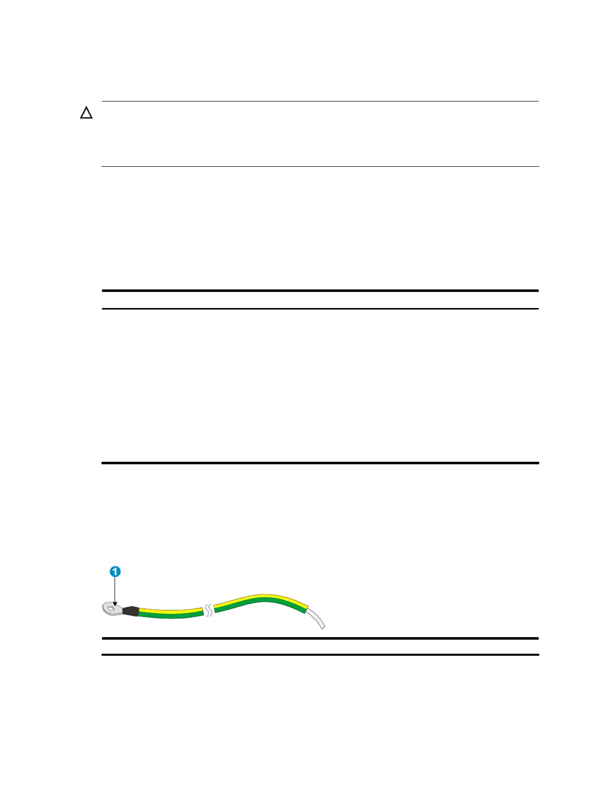
The S3100V2 Switch Series is provided with a yellow-green grounding cable. One end of the cable has
an OT terminal, and the other end is naked and soldered, as shown in Figure 37.
Figure 37 Grounding ca
ble
(1) OT terminal of the grounding cable
Grounding the switch with a grounding strip
When a grounding strip is available at the installation site, connect the grounding cable to the
grounding strip.

 Loading...


