25
During the operation, note the following guidelines:
• Make sure that the workbench is flat and sturdy.
• Ensure good ventilation and a space of 10 cm (3.94 in) around the chassis for heat dissipation.
• Avoid heavy objects on the switch.
• Some S3100V2 switches are fanless. Install them in an environment with good ventilation. To stack
switches one on another, keep at least a vertical distance of 1.5 cm (0.59 in) between equipment.
Mounting the switch on a wall
The S3100V2-8TP-PWR-EI can be mounted to a concrete or wood wall through wall-mounting brackets.
Follow these steps to mount the switch to a wall by using wall-mounting brackets:
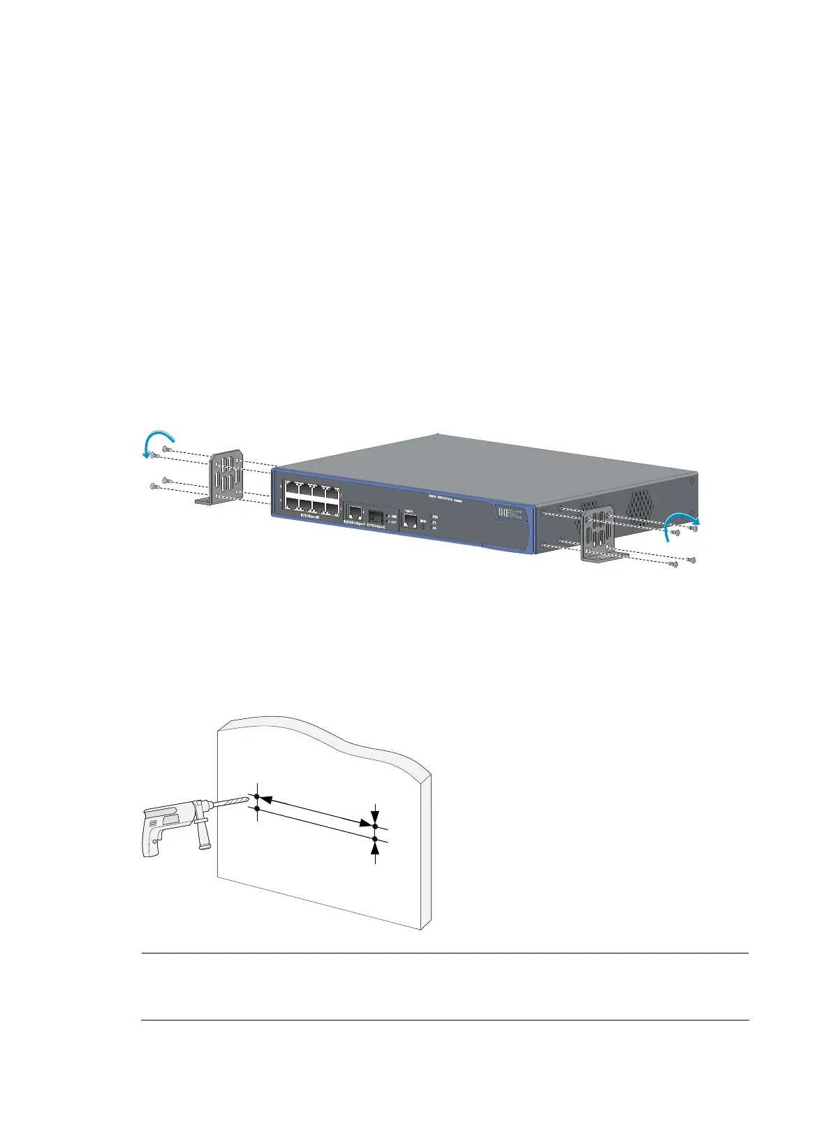
Step1 Use the screws supplied with the mounting brackets to install the mounting brackets to the switch, making
sure that the bottom edges of the mounting brackets at the same level with the switch bottom, as shown
in Figure 32.
Figure 32 Mount the swi
tch to the rack by using wall mounting brackets
Step2 Select a location on the wall where you want to install the switch. As shown in Figure 33, draw a
horizontal line measuring 323 mm (12.72 in) long. Make sure that the horizontal line is level. Drill two
holes for the mounting screws, one at each end of the line. Draw a vertical line measuring 31.8 mm (1.25
in) long from each end of the horizontal line, and then drill two holes.
Figure 33 Mount the switch to a wall
Xmm
Ymm
NOTE:
Make sure that the expansion anchors can be inserted into the holes when you determine the sizes and
depth of the four holes.

 Loading...


