5-4
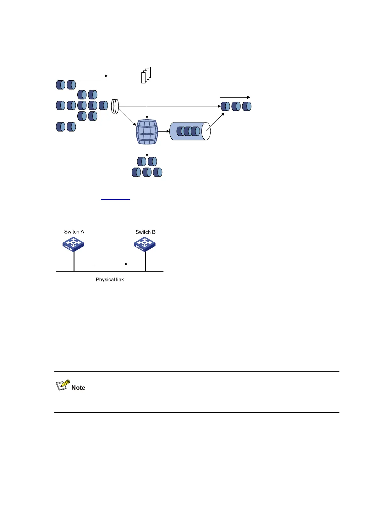
Figure 5-2 Schematic diagram for GTS
Token
bucket
Packets dropped
Packet
classification
Packets to be sent
through this interface
Packets sent
Tokens are put into the
bucket at the set rate
Queue
For example, in
Figure 5-3, Switch A sends packets to Switch B. Switch B performs traffic policing on
packets from Switch A and drops packets exceeding the limit.
Figure 5-3 GTS application
You can perform traffic shaping for the packets on the outgoing interface of Switch A to avoid
unnecessary packet loss. Packets exceeding the limit are cached in Switch A. Once resources are
released, traffic shaping takes out the cached packets and sends them out. In this way, all the traffic
sent to Switch B conforms to the traffic specification defined in Switch B.
Line Rate
Line rate supports rate-limiting traffic in the outbound direction.
The line rate of a physical interface specifies the maximum rate for forwarding packets (including
critical packets).
Line rate also uses token buckets for traffic control. With line rate configured on an interface, all
packets to be sent through the interface are firstly handled by the token bucket at line rate. If there are
enough tokens in the token bucket, packets can be forwarded; otherwise, packets are put into QoS
queues for congestion management. In this way, the traffic passing the physical interface is controlled.

 Loading...


