9-5
Priority Marking Configuration Example
Priority Marking Configuration Example
Network requirements
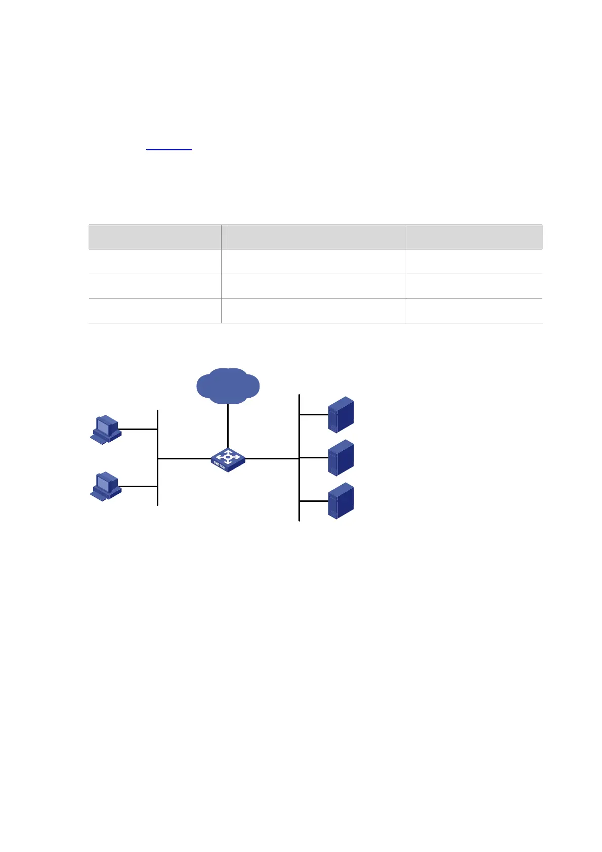
As shown in Figure 9-1, the enterprise network of a company interconnects hosts with servers through
Device. The network is described as follows:
z Host A and Host B are connected to GigabitEthernet 2/0/1 of Device.
z The data server, mail server, and file server are connected to GigabitEthernet 2/0/2 of Device.
Configure priority marking on Device to satisfy the following requirements:
Traffic source Destination Processing priority
Host A, B Data server High
Host A, B Mail server Medium
Host A, B File server Low
Figure 9-1 Network diagram for priority marking configuration
Internet
Host A
Host B
Device
Data server
192.168.0.1/24
Mail server
192.168.0.2/24
File server
192.168.0.3/24
GE2/0/1 GE2/0/2
Configuration procedure
# Create advanced ACL 3000, and configure a rule to match packets with destination IP address
192.168.0.1.
<Device> system-view
[Device] acl number 3000
[Device-acl-adv-3000] rule permit ip destination 192.168.0.1 0
[Device-acl-adv-3000] quit
# Create advanced ACL 3001, and configure a rule to match packets with destination IP address
192.168.0.2.
[Device] acl number 3001
[Device-acl-adv-3001] rule permit ip destination 192.168.0.2 0
[Device-acl-adv-3001] quit
# Create advanced ACL 3002, and configure a rule to match packets with destination IP address
192.168.0.3.
[Device] acl number 3002

 Loading...


