Page 26
Electrical Connections
54400_install.fm
Section 1
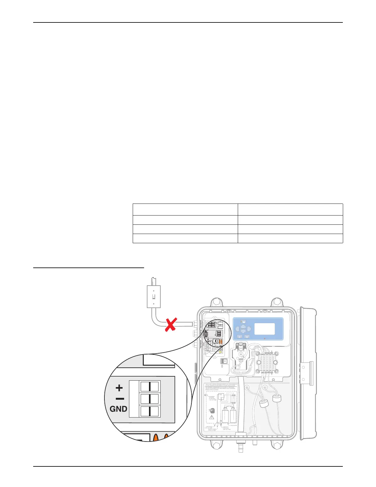
1.8.5 Recorder Output Connections
The recorder output is a 4–20 mA current-source output. Make recorder
connections with twisted-pair shielded wire and connect the shield at the
recorder, controlled component end or at the analyzer end. Do not connect
the shield at both ends of the cable.
Make wiring connections at the analyzer end as follows:
1. Make sure no power is supplied to the instrument.
2. Remove the Customer Access Cover (see Figure 8 in the manual).
3. Strip the insulation on each wire back ¼-inch. See Figure 12.
Note: Use a twisted-pair, shielded
cable. Use of non-shielded cable
may result in radio frequency
emission or susceptibility levels
higher than allowed.
4. Route the wire through an available strain relief.
5. Remove the connector from the instrument. See Figure 14 for
connector position.
6. Insert the wire ends into the connector (see the table below) until the
insulation seats against the connector as shown in Figure 12. (Do not
seat the insulation under the terminal pinch plates.)
7. Replace the connector and supply power to the instrument.
Figure 14 Recorder Connections
Recorder Wires Circuit Board Markings
Recorder + +
Recorder – –
Shield GND
SAMPLE IN
5 PSIG MAX
1/4IN. O.D.TUBE
AIR PURGE
.01CFM AT
20 PSIG MAX
¼ IN. O.D.TUBE
THIS CLASS A DIGITAL APPARATUS MEETS ALL REQUIREMENTS
OF THE CANADIAN INTERFERENCE CAUSING REGULATIONS.
CET APPAREIL NUMERIQUE DE LA CLASSE“A” RESPECTE
TOUTES LES EXIGENCES DU REGLEMENT SUR LE MATERIEL
BROUILLEUR DU CANADA.
SAMPLE DRAIN
1/2 IN. I.D.TUBE
CASE DRAIN
1/2 IN. I.D.TUBE
ENCLOSURE
115V
J4
F2
F1
GND
NEU 2Æ
HOTT 1Æ
NO
NO
NC
NC
GND
COM
COM
J9
K1
K2
115V
!
R
E
A
G
E
N
T
EXIT ENTER
Chlorine
mg/L
Alarms
µg/L
MENU
+
BUFFER
1
2
3
123
1
2
3
ON
OFF
Make sure no power is
supplied to the instrument.
123