Page 61
54400_network.fm Hach Network Interface Card for the CL17 Chlorine Analyzer
Appendix B Hach Network Interface Card for the
CL17 Chlorine Analyzer
The CL17 analyzer can be purchased with a Hach Network Interface Card
that allows the analyzer to be attached via the AquaTrend
®
software to one
master AquaTrend Interface, one Serial Input/Output (SIO) Module, one
Signal Output Module (SOM) with two relays and one recorder output, and
two MOD I/Os. Remote AquaTrends and Digital Display Modules are not
supported. Integration of the CL17 Analyzer into an existing Hach Network is
discussed in the following section. Refer to the AquaTrend Interface
Instruction Manual for complete details on configuring the Hach network.
1. Route a Hach-approved network cable to the CL17 Analyzer. Route the
network cable through the middle wiring access hole in the CL17 housing.
(This hole is also used for routing Recorder output wiring.) Use
appropriate hardware to maintain the NEMA 4X and IP66 ratings.
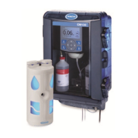
2. Strip the ends of the network cable. Strip back the wire insulation ¼ inch.
3. Refer to Figure 23 and insert each bare wire end into the 3-pin connector
using the information in Ta bl e 7 . Make sure the wire insulation is seated
against the connector. Do not leave any of the bare wire exposed.
4. Plug the terminated cable into J1 on the Interface Card.
5. Reattach the access panel to the instrument enclosure with the
two screws.
6. Reapply power to the CL17 Analyzer.
Figure 23 Proper Wire Preparation
Table 7
Position Signal Wire color
1NET_AWhite
2NET_BGreen
3 GND Shield
3
2
1
Strip ¼ inch
Wire insulation should be seated against connector.
Do not leave any of the bare wire exposed.
Ground Wire