31
Installation
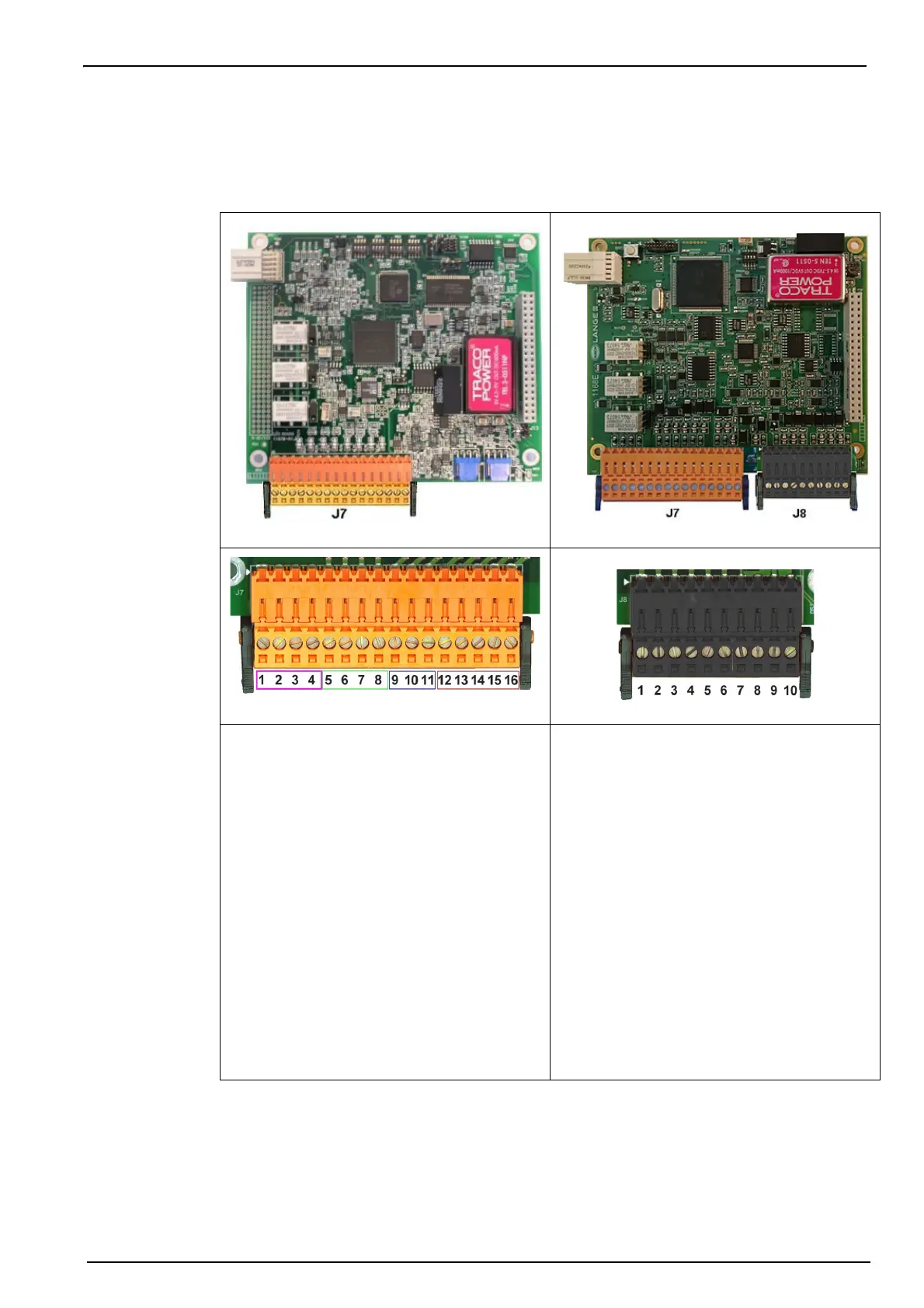
3.6.4 Measurement board
The different measurement boards for the LDO and TC sensors are illustrated in Figure 14 and
Figure 15 below. The type of board is easily identified by the J8 sensor connector. This
connector is only present on TC boards.
Figure 14 LDO Measurement board
Figure 15 TC Measurement board
Figure 16 Connector J7
Figure 17 Connector J8
Connector J7 (inputs & outputs)
Measurement alarms relays
1. Common
2. Output relay 1
3. Output relay 2
4. Output relay 3
Note: Relays N.O. or N.C. depends on the jumper
position on the relays. Refer to Measurement alarm
relays on page 32.
Analog current (or voltage) outputs
5. Analog GND
6. Output 1
7. Output 2
8. Output 3
Digital inputs
9. Hold input. To deactivate the sensor from
a PLC system, connect a dry contact
between J7.9 and J7.12
10. Not used
11. Not used
12. Digital GND
13. to 16. Not used
 Loading...