32
Installation
3.7 Measurement alarm relays
The following table shows the relay number associated with the numbered connection for each
sensor type:
Analog inputs (when ext. press. sensor is
directly connected)
14. GND
15. Green: Input ext. press. sensor P+
16. White: Input ext. press. sensor P-
17. Red: Output ext. press. sensor +
18. Black: Ground (GND)
Analog inputs (when ext. press. sensor
extension, Part N° 32548.xx, is used)
12. GND
13. Green: Input ext. press. sensor P+
14. Yellow: Input ext. press. sensor P-
15. White: Output ext. press. sensor +
16. Brown: Ground (GND)
Note: On multi channel systems, the external pressure sensor must be wired to the channel 1
measurement board, but the signal is used to compensate all channels.
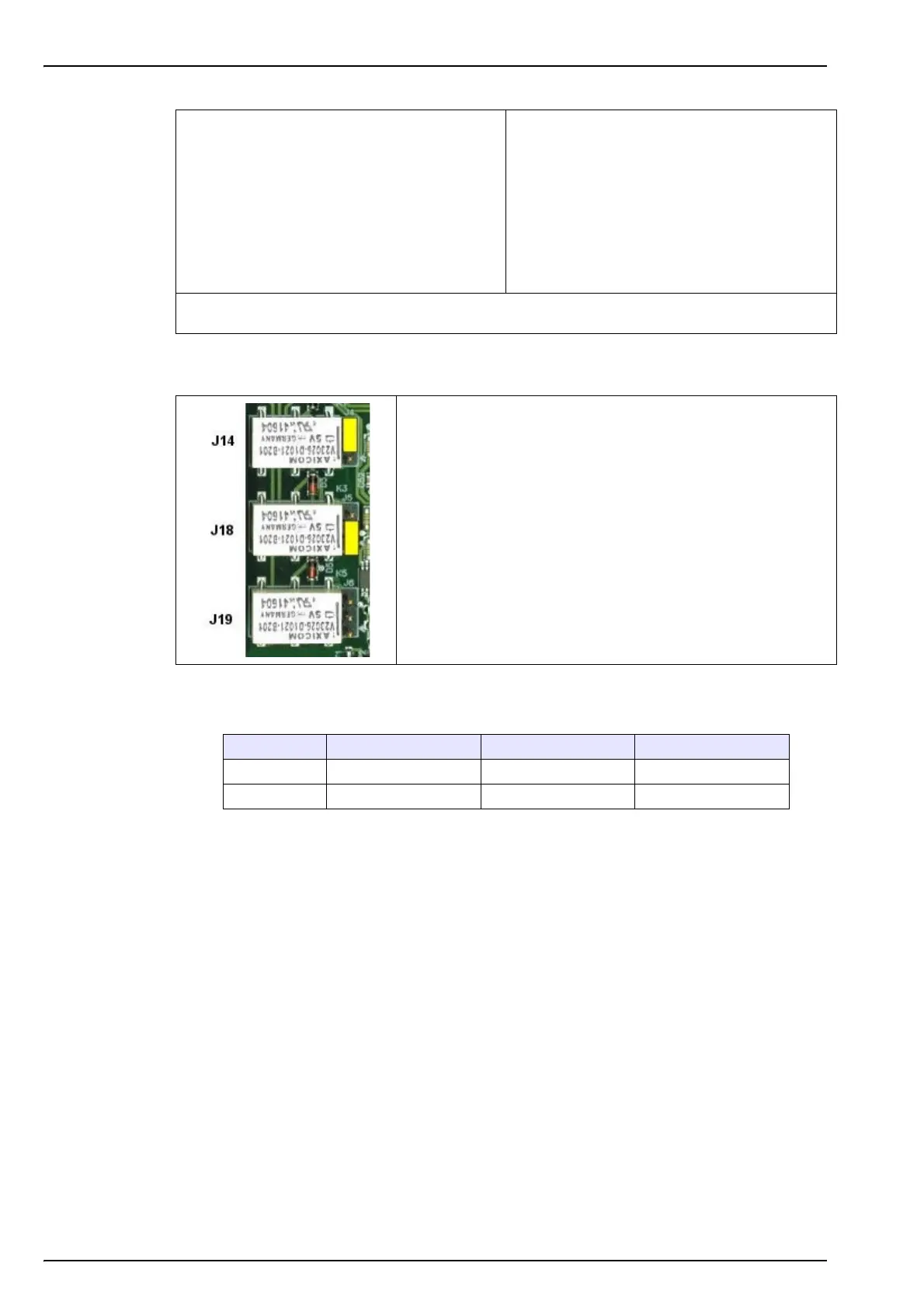
The three output relays are located on the measurement
board.
They can be individually configured to Normally Open (NO) or
to Normally Closed (NC) by physically moving the jumper on
each relay.
The LDO sensor measurement board is used as an example:
• Upper relay (J14) is set to NC
• Middle relay (J18) is set to NO
• Lower relay (J19) is shown with no jumper
Sensor type Relay 1 Relay 2 Relay 3
LDO
J14 J18 J19
TC
J4 J5 J6
 Loading...