Section 3 Product overview
3.1 Analyzer overview
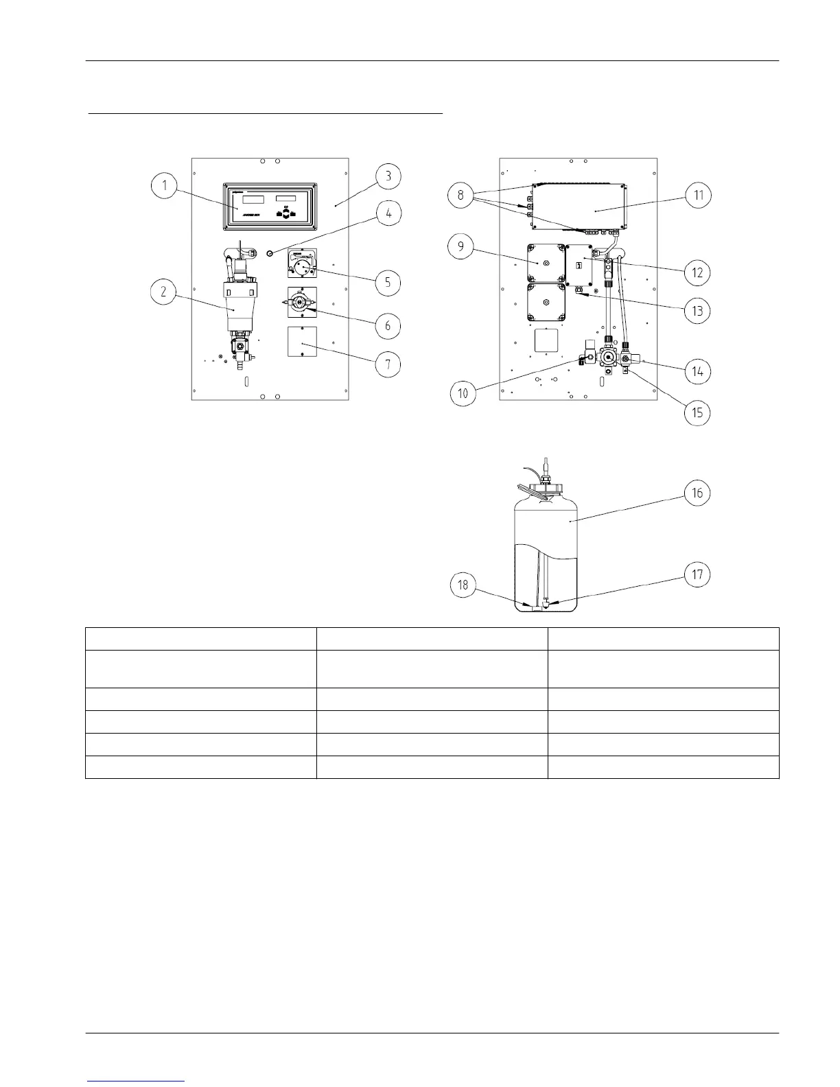
Figure 3 Front and rear view (panel mount illustrated)
1 Electronic unit 7 Space for additional pump 13 Power supply connection
2 Measurement chamber (see
Figure 4 on page 10)
8 Input/Output connections 14 Rinse valve
3 19 inch panel 9 Reagent pump cover 15 Sample valve
4 Main switch 10 Compressed air valve 16 Reagent canister
5 Peristaltic pump 11 Electronic unit (rear) 17 Level detector
6 Micro piston pump 12 Power supply box 18 Tube weight
9
 Loading...


