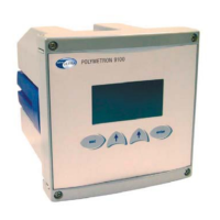
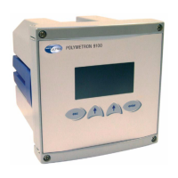
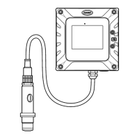
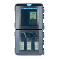
Figure 13 Rinsing and dilution assembly
In the above illustration the rinsing system is shown on the left and the dilution system on the right.
1 Input block (already installed on the
analyzer)
8 PE tubing 4/6 15 PE tubing 3.2/6.4
2 Sample valve (already installed on
the analyzer)
9 Outlet tubing 3/5 16 Electric cable
3 Flow block 10 Barbed elbow fitting, sample inlet
(already installed on the analyzer)
17 Flow rate adjustment screw
4 Male/male fitting G3/8 11 Barbed elbow fitting, rinse water
inlet (already installed on the
analyzer)
18 Compressed air inlet
5 PE tubing 10/12 (already installed on
the analyzer)
12 Control valve 19 Compressed air outlet to (20)
6 PE tubing 6/8 (already installed on
the analyzer)
13 Dilution assembly 20 Compressed air inlet from (19)
7 PE tubing 3/5 14 PE tubing 3.2/6.4 21 Rinse valve (already installed on
the analyzer)
Install the rinsing assembly as follows (the numbers in brackets refer to Figure 13):
1. Remove the rinse valve (21).
2. Unscrew the sample valve (2) from the panel.
3. Install the sample valve (2) on the flow block (3) using the supplied fitting (4).
4. Screw the new assembly (2 and 3) back on the panel using the two screws from the
sample valve.
5. Install the rinse valve (21) on the flow block (3) using the supplied fitting.
6. Install the PE tubing 10/12 (5) between the flow block (3) and the input block (1).
7. Install the PE tubing 6/8 (6) between the flow block (3) and the sprinkler.
8. Install the PE tubing 3/5 (7) between the flow block (3) and the input block (1) for
rinsing, using the supplied fitting.
9. Install the PE tubing 4/6 (8) on the flow block (3) for sample drainage.
10. Install the PE tubing 3/5 (9) on the flow block (3) for rinse water drainage.
Additional options
41

 Loading...


