Harris Corporation Constellation®
The Constellation Radio 3-3
CONSTELLATION
RADIO
CONFIGURATIONS
When connecting an OEM M1-3 multiplexer to a
Constellation 3xDS3 or 4xDS3 radio, DS3 errors might
be observed for shorter cable lengths. This can be
caused by reflections in the cable connecting the
equipment. Installing a 3dB attenuator in series with
the DS3 cable when the length is less than 10 feet may
be required. For additional information go to the Harris
MCD Premier website at
https://premier.harris.com/microwave.
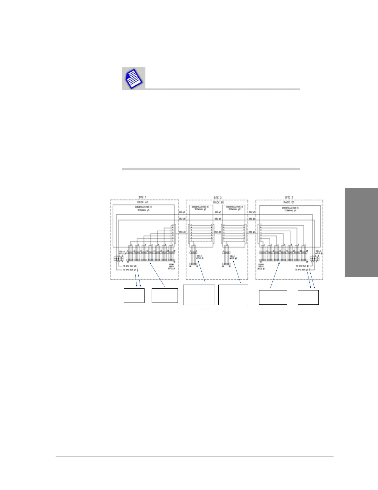
Figure 3-1: Traffic Plan Example for 3xDS3 (2xDS3+28 DS1)
Back to Back Terminals “Repeater”Terminal Terminal
Drop 4 DS1’s (DS2 # 1)
from Site 1 DS3 #3.
For NP, add 1 M12
card. For MHSB, also
add Protection M12
and 7 filler cards.
To External
M13 MUX’s
for DS3 #1
and DS3 #2
Access 28xDS1’s
from DS3 #3
w/Constellation
integral mux
Add 4 DS1’s (DS2 #1)
For NP, add 1 M12
card. For MHSB,
also add Protection
M12 and 7 filler
cards.
Access 28xDS1’s
from DS3 #3
w/Constellation
integral mux
M12 Cards required only when DS1’s are added or dropped!
No external M13 mux required!
A different DS3 can be selected from site to site!
Similarly, 4xDS3 provides a 3xDS3 + 28xDS1 interface,with the first 3xDS3’s available for DS1 access.
To External
M13 MUX’s
for DS3 #1
and DS3 #2