Harris Corporation Constellation®
ACU Configuration and Mechanical Drawings 6-3
ANTENNA
COUPLING UNIT
(ACU)
List of ACU Mechanical Drawings
•ACU, nonprotected (top view) ........................................................... 6-3
• ACU, nonprotected (front view) ........................................................ 6-4
• ACU, hot standby (top view) .............................................................. 6-4
• ACU, hot standby (front view) ........................................................... 6-5
• ACU, hot standby Transmitters, space diversity
Receivers (top view) ........................................................................... 6-5
• ACU, hot standby Transmitters, space diversity
Receivers (front view) ........................................................................ 6-6
• ACU, hot standby/frequency diversity 2 antennas
(T/R, T/R) (top view) ......................................................................... 6-6
• ACU, hot standby/frequency diversity 2 antennas
(T/R, T/R) (front view) ...................................................................... 6-7
• ACU, repeater/dual terminal .............................................................6-8
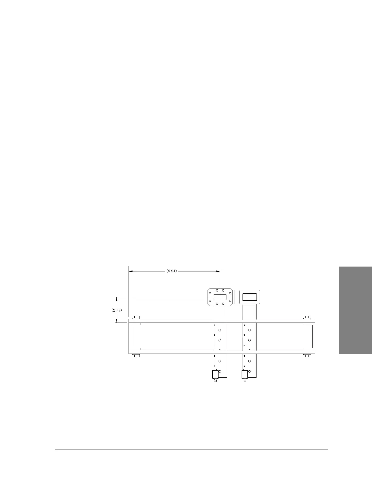
ACU Mechanical Drawings
Figure 6-1: ACU, nonprotected (top view), mechanical
drawing
TX1
RX1