Harris Corporation Constellation®
Configurations 3-11
CONSTELLATION
RADIO
CONFIGURATIONS
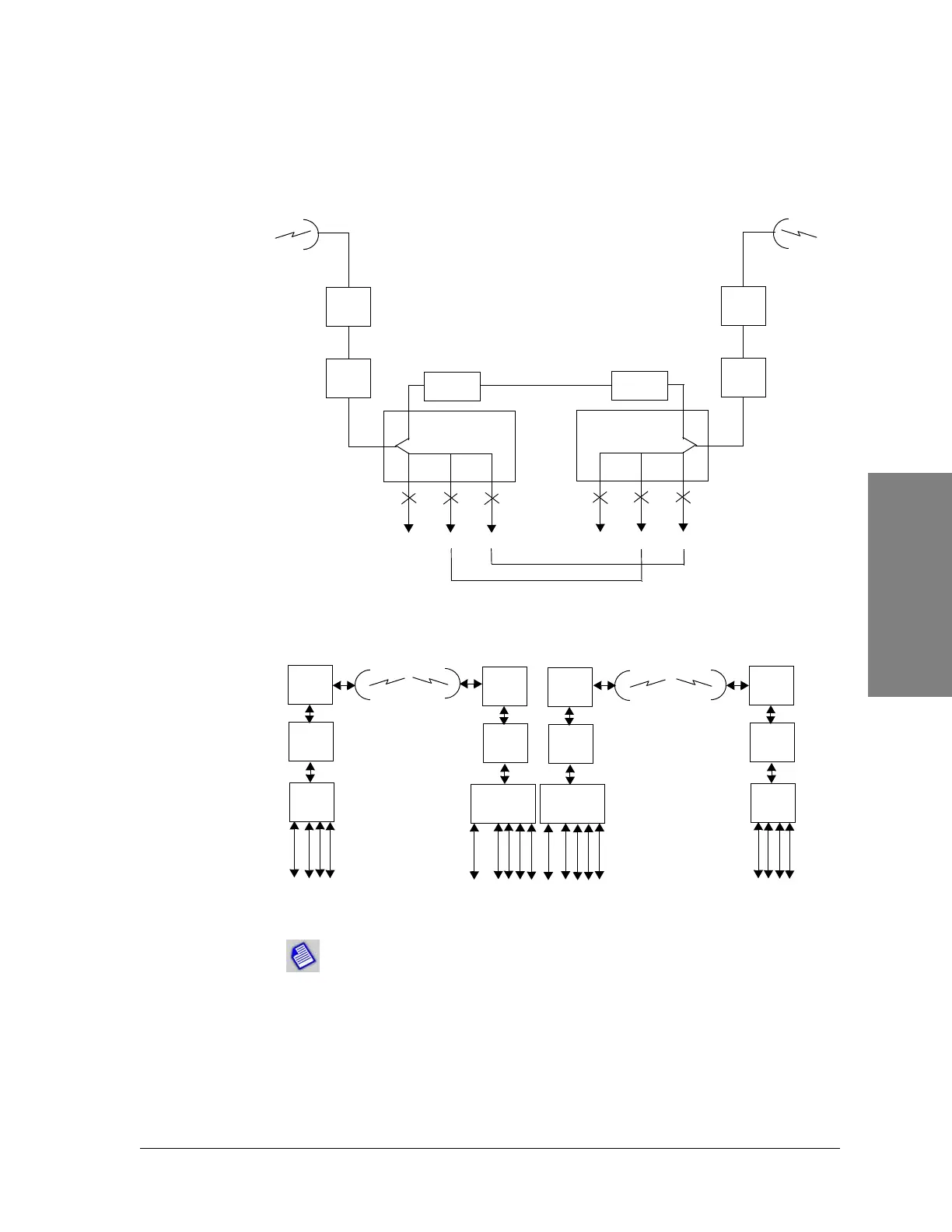
Figure 3-12: 3xDS3 configured as 2xDS3 + 28DS1 back-to-
back terminals
Figure 3-13: 3(4)xDS3 configured as 2(3)xDS3 + 28DS1
terminal, ADM repeater, and 3(4)xD3 terminal
RADIO
A
MODEM
A
DS3 HLM
JF
4-28 DS1s
SERVICE
CHANNEL
JF
DS3
JF
DS3
RADIO
A
MODEM
A
DS3 HLM
JF
DS3
SERVICE
CHANNEL
JF
DS3
JF
4-28 DS1s
MUX
MODEM
28 T
DS3 #2
RF
RF
RF
RF
2/3DS3+28T Terminal
3/4DS3 ADM Repeater
3/4DS3 Terminal
MUX
MODEM
MUX
MODEM
MUX
MODEM
DS3 #2
DS3 #2
DS3 #3
DS3 #3
DS3 #3
DS3 #3
DS3 #4
DS3 #4
DS3 #4
DS3 #4
DS3 #2
DS3 #1
DS3 #1
DS3 #1
8 T
8 T
When ADM is used, non-dropped DS1 channels pass between radios on the DS3 channel.
The added DS1s are mapped into the DS3 entering the radio. 3/4DS3 + ADM should not
be used at a terminal stie without a DS3 input on the ADM channel. At these terminal sites,
use 2/3 DS3 +28T. If not all 28T are needed at the terminal site, sub-equip the M12s.