9
Sultan 234 Series
Admittance Smart Switch Series
Manual
Rev 1.2, June 2008
MOUNTING
Probes can be mounted from the top,
side and bottom.
Points to consider when mounting:
A. Material Infeed Clearance
Install the probe away from the infeed to
minimize the inuence of build-up and
impact forces, and to avoid false trigger-
ing from product ow.
B. Wall Clearance
Install the probe far enough away from
the wall to prevent the probe or cable
from coming into contact with the vessel
wall. Avoid creating a conned area
where material could build-up over time.
See note
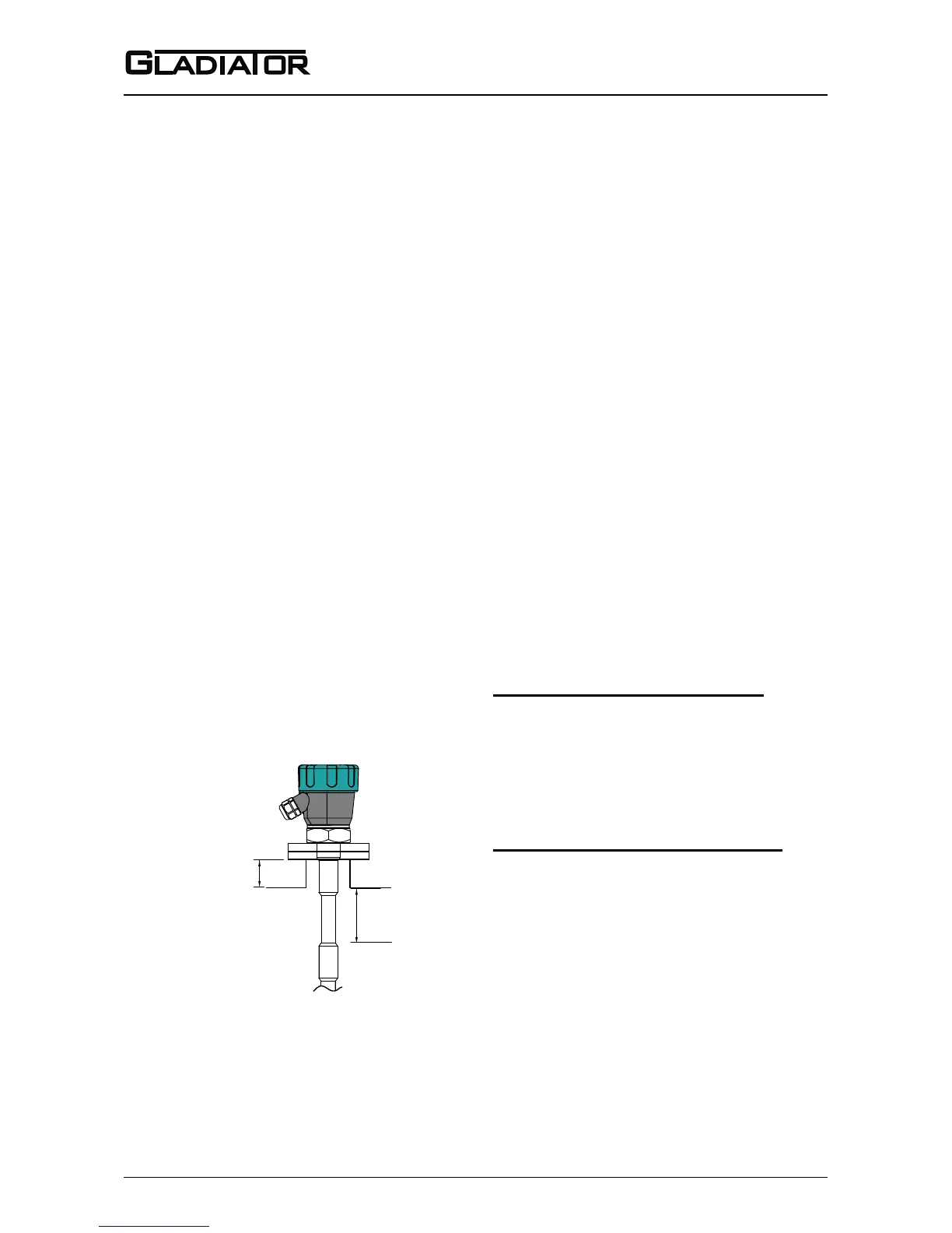
C. Nozzle Clearance
Where possible, ensure the probe guard
has at least 100mm clearance from the
nozzle.
D. Top mounting
When top mounting, ensure adequate
clearance is provided between probe
and wall. Avoid creating a conned area
where material could build-up over time.
In the case of cable probe versions,
ensure enough clearance is provided
between the probe and wall to allow for
build-up of material occurring on the
wall.
See note
E. Side mounting
It is highly recommended to install any
side mounted probe at a downward
angle of 30-45º. Use a protection plate
for side mounting where the probe may
be subject to impact strain or collapsing
material.
F. Bottom mounting
Bottom mounting is not recommended.
Only mount from the bottom if no build-
up of material occurs. If low level mount-
ing is required, suitable options are
shown in the diagram on page 10.
CORRECT MOUNTING NOTES:
(Refer to picture on page 10)
Select correct probe for high tem-
perature applications.
Allow adequate air ow for cooling ex-
tensions dissipate heat.
INCORRECT MOUNTING NOTES:
Incorrect mounting because the
probe is too close to the wall or roof.
Positioning too close to a wall or roof
will limit probe sensitivity. Material may
build-up between the probe and the
vessel.
Incorrect mounting because the
probe’s guard is mounted inside the
nozzle. The correct arrangement is for
the guard to protrude out of the mounting
pipe at least 100mm. Product will build-
up in the nozzle.