16 Hayes Modem Installation Guide
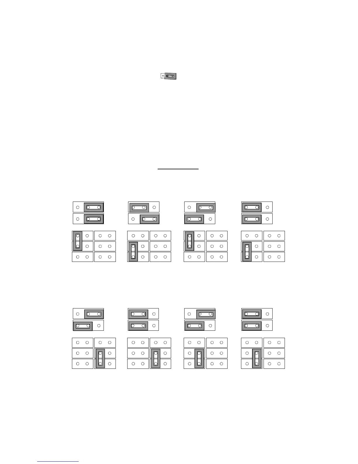
JP2
(The shaded area indicates jumper position.)
Use one of the jumper combinations as shown in the following
diagram to set COM1 through COM8. The JP1 setting determines
IRQ, and the JP3 and JP4 settings determine the address of the fax
modem. To set the appropriate COM port jumper combination, use
the settings you determined earlier in this chapter. The fax modem
is pre-set at the factory for COM 4, IRQ 3.
Jumper Settings
JP1
JP1
JP1
JP3
JP3
JP3
JP3
JP3
JP3
JP4
JP4
JP4
JP4
JP4
JP4
Address 03F8
IRQ4
COM5
Address 03E8
IRQ2
Address 02F8
IRQ3
COM6
Address 02E8
IRQ2
Address 03E8
IRQ4
COM7
Address 03E8
IRQ5
IRQ3
COM8
IRQ5
If you set your modem to one of the settings (COM1 to COM8) as
shown above, you can proceed to Installing Your Fax Modem.