15
Clip
HBMA0114-6.3 en
4 Setup
If all cables are connected, proceed as follows:
• Connect transducer cable
• Switch on supply voltage.
• Slacken screw on upper right housing edge and hinge down housing cover.
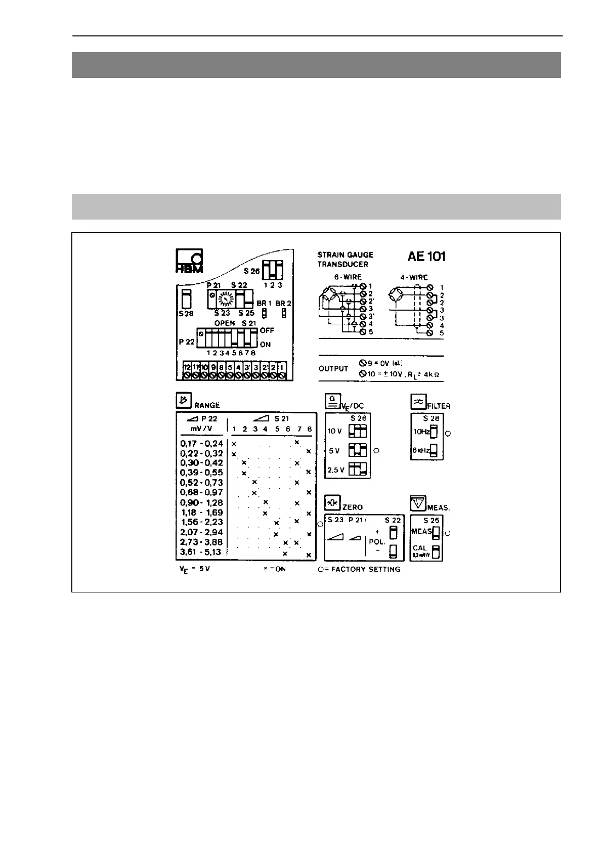
4.1 AE101 Measuring amplifiers
Fig. 4.1: Stick-on label in housing
• Connection method
The standard transducer connection-method is the 6-wire technique (with two
sensor lines). If the transducer is to be connected using a 4-wire circuit, the
terminals 2 and 2’ and 3 and 3’ must be provided with jumper wires.