22
Clip
HBM A0114-6.3 en
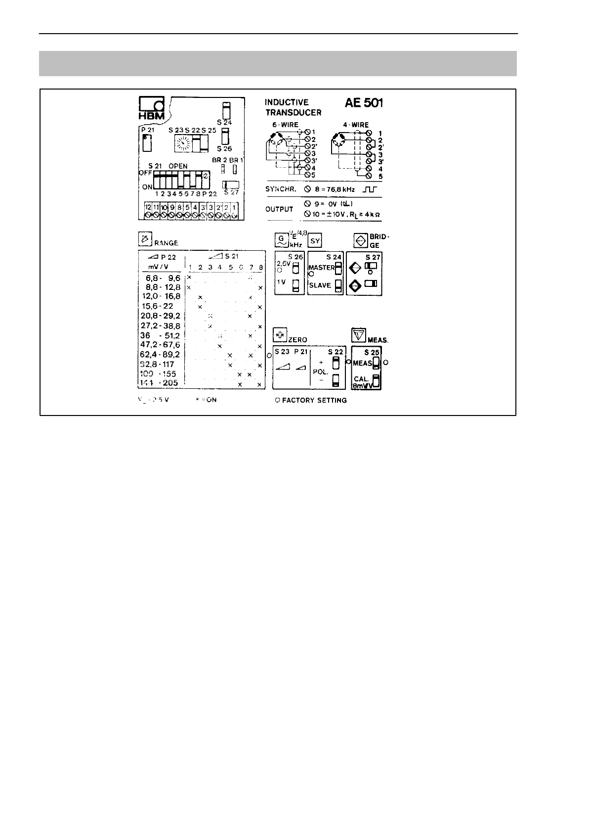
4.3 AE501 Measuring amplifier
Fig. 4.3: Stick-on label in housing
• Connection method
The standard transducer connection-method for inductive halfbridges is the
5-wire technique for inductive fullbridges the 6-wire technique. If the trans-
ducer is to be connected using a 3-wire circuit (inductive half bridge) or a
4-wire circuit (inductive full bridge), the terminals 2 and 2’ and 3 and 3’ must
be provided with jumper wires.
• Bridge type
Use switch S27 to select the bridge type (inductive half bridge, inductive full
bridge).
• Bridge excitation voltage
Use switch S26 to select the bridge excitation voltage V
E
according to the in-
ductance L
B
of the half-bridge or full-bridge transducer. When using SI01
safety barriers, the bridge excitation voltage must in any case be adjusted
to 1 V.
 Loading...


