25
Clip
HBMA0114-6.3 en
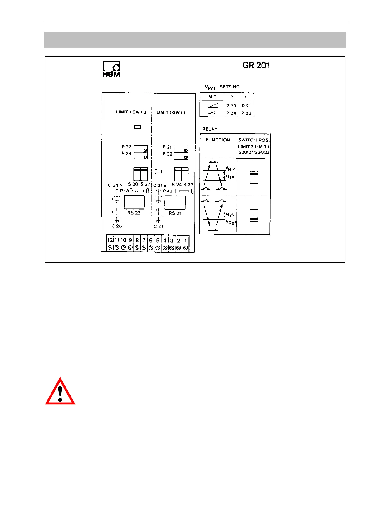
4.4 GR201 Double limit-value switch
M 4
M 3
Fig. 4.4: Stick-on label in housing
• Reference voltage
Use the potentiometers P21 (coarse) and P22 (fine) for limit 1 or P23 (coarse)
and P24 (fine) for limit 2 to adjust the relay response point (reference voltages
V
Ref1
and V
Ref2
). The reference voltages V
Ref1
and V
Ref2
are available at the
measuring points M4 (for limit1) and M5 (for limit 2). Connect a digital voltme-
ter to adjust the reference voltages as follows:
Limit 1 to measuring point M4 and terminal 4
Limit 2 to measuring point M3 and terminal 9
CAUTION
When the amplifier and limit value switch are supplied from several
power supply units their ground connections have to be interconnected.