18
T12
HBM
A24633.0en/de
usually be overcome by connecting the rotor directly to ground, for instance
by a wire loop. The stator should be fully grounded in the same way.
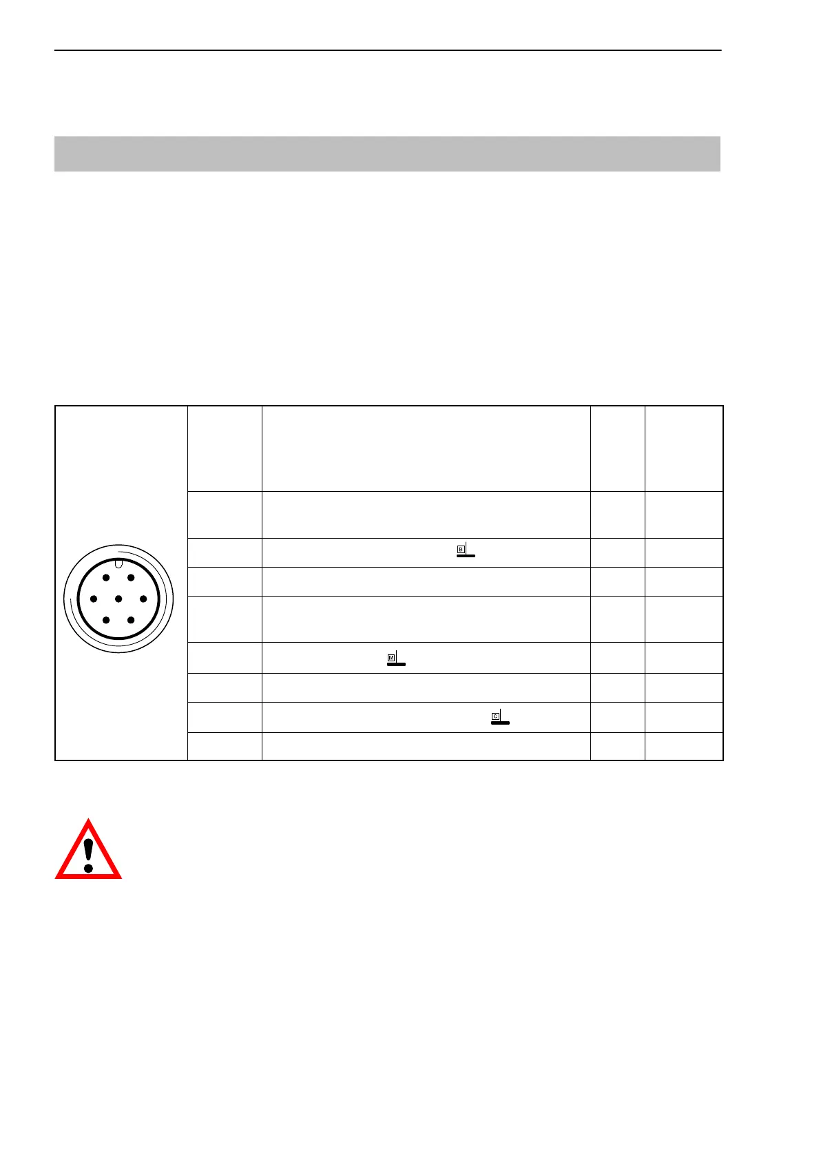
4.3 Connector pin assignment
The stator housing has two 7pin device plugs (Binder 723) and one 8pin
device plug.
The supply voltage connections and shunt signal connections of plugs 1 and 3
are each electrically interconnected, but are protected against compensating
currents by diodes. There is also an automatically resetting fuse (multifuse) to
protect the supply connections against overload by the stator.
Assignment for plug 1:
Supply voltage and frequency output signal.
61
5
72
4
3
Binder 723
Top view
Binder
pin
Assignment Color
code
SubD
con
nector
pin
1 Torque measurement signal (frequency output;
5V
1)
wh 13
2 Supply voltage 0V; bk 5
3 Supply voltage 18V to 30V bu 6
4 Torque measurement signal
(frequency output; 5V
1)
) rd 12
5
Meas. signal 0V; symmetrical
gy 8
6 Shunt signal trigger 5V to 30V gn 14
7
Shunt signal 0V;
gy 8
Shielding connected to enclosure ground
1)
Complementary signals RS422; for cable lengths of 10 m and longer, we recommend to
use a termination resistor R=120 ohms between wires (wh) and (rd).
CAUTION
Torque flanges are only intended for operation with a DC supply vo ltage.
They must not be connected to older HBM amplifiers with squarewave
excitation. This could destroy the connection board resistances or
cause other faults in the amplifiers.