9
T40
HBMA24633.0en/de
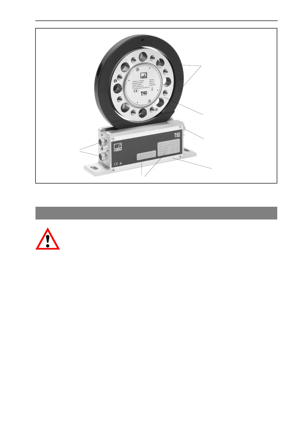
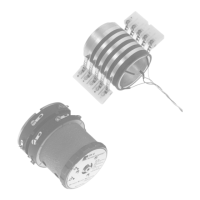
Stator housing
Rotor
Antenna segments
Type plate
Connector plugs
Connector plug
Fig.2.1: Mechanical construction
3 Mechanical installation
WARNING
Handle the torque flange carefully. The transd ucer might suffer
permanent damage from mechanical shock (dropping), chemical effects
(e.g. acids, solvents) or thermal effects (hot air, steam).
With alternating loads, you should cement the rotor connectionscrews
into the mating thread with a screw locking d evice (medium strength) to
exclude prestressing loss due to screw slackening.
An appropriate shaft flange enables the T40 torque flange to be mounted
directly. It is also possible to mount a joint shaft or relevant compensating
element directly on the rotor (using an intermediate flange when required).
Under no circumstances must the permissible limits specified for bending
moments, lateral and longitudinal forces be exceeded. Due to the T40
measurement flange’s high torsional stiffness, dynamic shaft train changes
are kept to a minimum.