14
T12
HBM
A24633.0en/de
WARNING
With alternating load: Use a screw locking device
(e.g. LOCTITE
)
no. 242) to glue the screws into the counter thread to
exclude prestressing loss due to screw slackening.
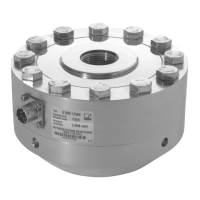
3. Tighten all screws with the specified tightening torque (Tab. 4.1).
4. For further mounting of the shaft run, there are eight tapped holes on the
rotor. Also use screws of property class 10.9 or 12.9 and fasten with the
tightening torque specified in Table 4.1.
CAUTION
With alternating loads, use a screw locking device to cement the
connecting screws into p lace. Guard against contamination from
varnish fragments.
Measuring range
(NVm)
Fastening screws
(Z)
1)
Fastening screws
Property class
Prescribed
tightening torque
(NVm)
500 M10
10.9
67
1 k M10 67
2 k M12 115
3 k M12 12.9 135
Table 3.1: Fastening screws
1)
DIN EN ISO 4762; black/oiled/m
tot
= 0.125
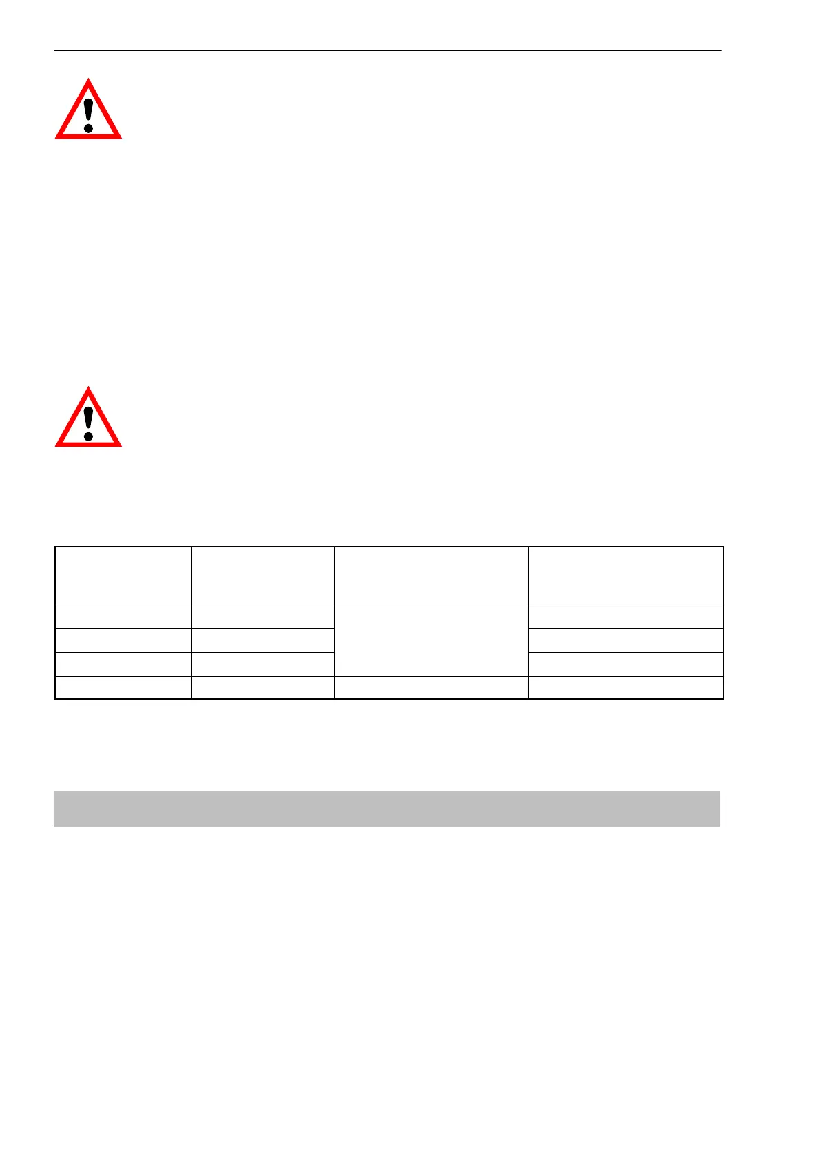
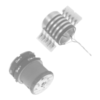
3.5 Installing the stator
On delivery, the stator has already been installed and is ready for operation.
The upper antenna segment can be separated from the stator, for example,
for maintenance or to facilitate stator mounting.
If your application does not require the stator to be dismantled, proceed as
described in points 2., 5., and 6.