Structure and mode of operation
TIM40 A02590_04_E00_00 HBM: public 13
5 Structure and mode of operation
U/I
Profibus
CANopen
(optional)
TIM40
Torque interface
module
38 125 MW/s
F
TP2
1...3000 Hz
D/A
"10V
(12"8)mA
D/F
TP1
1...3000 Hz
Ethernet
UDP
Ethernet
T40‐TMC
FPGA
Anybus
Anybus
module
OPTION
1
Input
X3
Output X6
Output X7
Output X5
Output X4
2 2
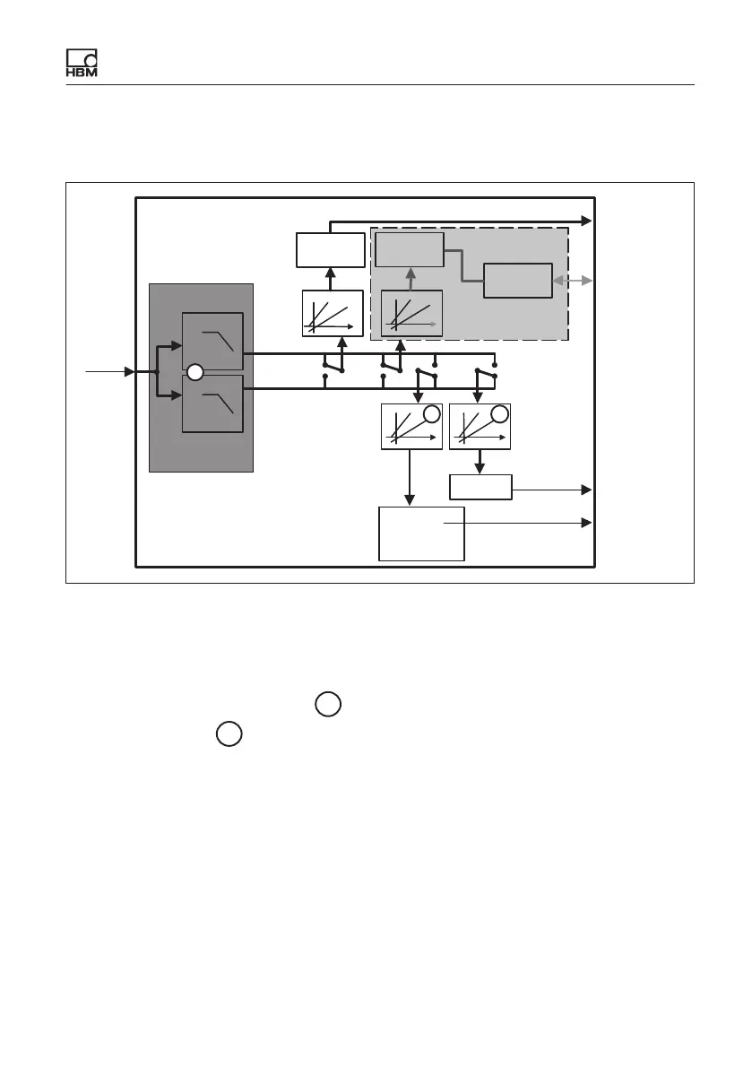
Fig. 5.1 Signal flow TIM40
The torque interface module TIM40 receives the measurement data of the T40
stator (38 125 measured values/s, 16 Bit) at input X3.
Two deactivatable digital filters
1
are available for all subsequent signal
routes and scaling
2
for each output.
Scaling and filtering are set via the integrated web server. You can implement
all settings from the PC with a web browser via an Ethernet connection.
The processed measurement signals are then available at analog output X4,
frequency output X5 and the Ethernet interface X6 (and optionally Anybus
,
output X7).
The supply voltage can be looped through without extra circuitry measures
(from X1 to X3) to supply the T40 transducer.