Electrical connection
TIM40 A02590_04_E00_00 HBM: public 21
9 Electrical connection
9.1 General information
To make the electrical connection between the torque transducer and the
amplifier, we recommend using shielded, low‐capacitance measurement cables
from HBM.
With cable extensions, make sure that there is a proper connection with mini
mal contact resistance and good isolation. All plug connections or swivel nuts
must be fully tightened.
Do not route the measurement cables parallel to power lines and control cir
cuits. If this cannot be avoided (in cable pits, for example), maintain a minimum
distance of 50 cm and also draw the measurement cable into a steel tube.
Avoid transformers, motors, contactors, thyristor controls and similar stray‐field
sources.
9.2 Shielding design
The cable shield should be connected to the protective housing according to
the Greenline concept. This encloses the measurement system in a Faraday
cage. It is important that the shield is laid flat on the housing ground at both
ends of the cable. Any electromagnetic interference active here does not affect
the measurement signal.
In the case of interference due to differences in potential (compensating cur
rents), the connection between operating voltage zero and the housing ground
must be cleared at the amplifier and a potential equalization line established
between the stator housing and the amplifier (copper wire, 10 mm
2
wire cross‐
section).
9.3 Connector pin assignment
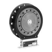
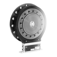
The TIM40 housing has 5 connector blocks with attached spring‐loaded termi
nals (Phoenix Combicon 5 mm), an Ethernet socket and a slot for holding an