WE2111
A3983-1.0 en/de/fr 17
6 Connecting load cells
This section describes how to connect one or more load
cells.
You can connect a maximum of 16 SG load cells in a full
bridge circuit with a bridge resistance of 350Ω each.
Transducer excitation is implemented in the basic device
WE2111 with 5V
DC
(bridge excitation voltage).
We recommend connecting the load cells via a suitable
junction if several load cells are connected, e.g. the HBM
model VKK2-8.
Important
Not all load cells can be connected in parallel. Refer to
the operating manual of the load cells to see if this is
possible.
For EMC reasons, a double shielded cable is
advantageous for connecting the load cell(s), e.g. HBM
model 4-3301.0071 with 3 ∗ 2 ∗ 0.14 m
2
.
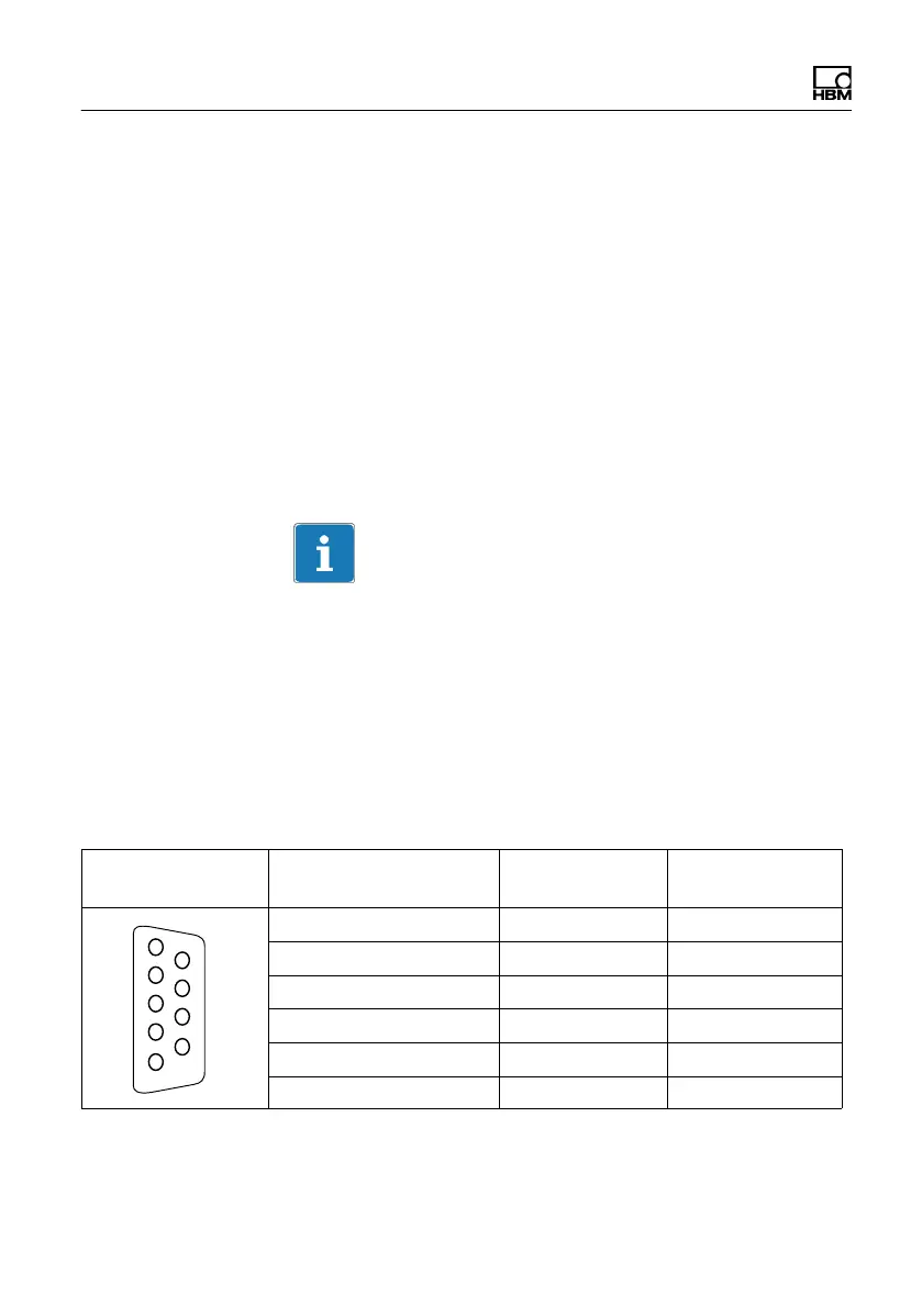
Contact assignment
Connector socket Function Contact No.
(Pin/Imprint)
HBM color code
1
5
6
9
Excitation voltage (+) 1 (+ Ex) BU (blue)
Excitation voltage (-) 3 (- Ex) BK (black)
Sense lead (+) 2 (+ Sn) GN (green)
Sense lead (-) 4 (- Sn) GY (gray)
Measurement signal (+) 9 (+ Sg) WH (white)
Measurement signal (-) 8 (- Sg) RD (red)