Description of the Hardware EPC9 Manual 10
2. Description of the Hardware
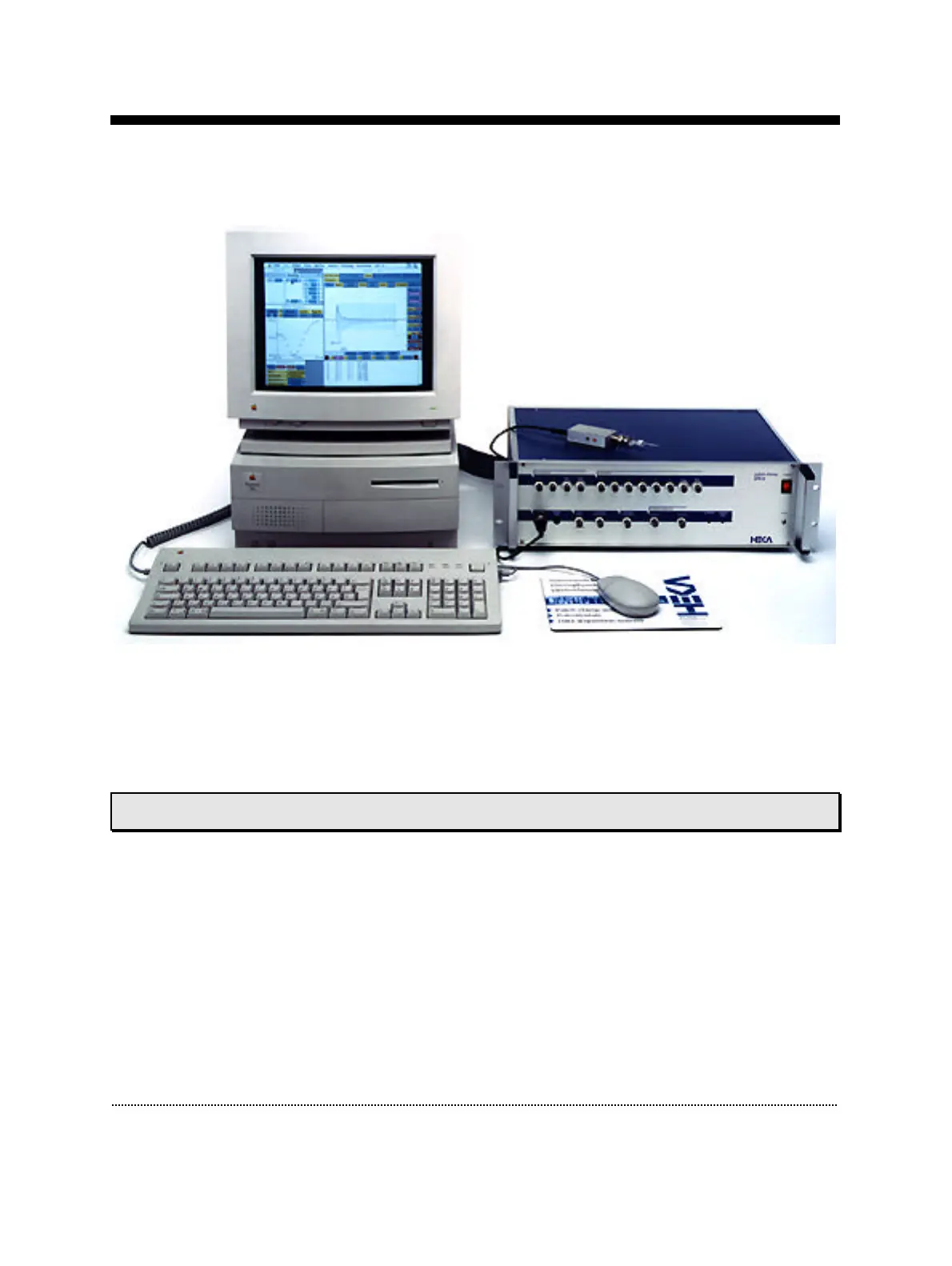
The hardware components of the EPC9 patch-clamp system consist of the head stage
(or probe), the amplifier main unit with the integrated ITC-16 interface board, and
the computer system. Specific information about the hardware installation is given
below in Chapter 3. Installation on page 16.
Probe
The probe, or “head stage” of the EPC9 is contained in a small enclosure designed to
be mounted on a micromanipulator and directly attached to the recording
micropipette. It contains the sensitive amplifier that constitutes the current-to-
voltage converter, as well as components for injecting test signals into that amplifier.
On the probe are the following connectors:
Input Connector: This is a Teflon-insulated BNC connector. The standard pipette
holder plugs directly into this connector; the center pin is the amplifier input, and
the shield is driven with the command potential Vp.