Testing the EPC9 EPC9 Manual 23
Step 2: ”On-Cell” Voltage-Clamp Recording
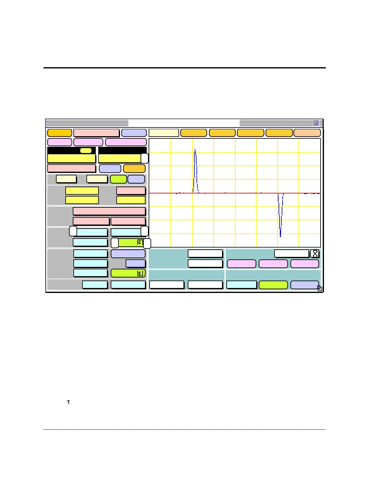
Now move the switch of the model circuit to the center position which leaves only a
capacitance of about 6 pF connected. This simulates a Giga-Ohm seal and the C-fast
controls can be used to cancel the capacitive spikes resulting from the stimulus test
pulse.
In order to see the small currents resulting from the high resistance of the model
circuit, set the gain to 50 mV/pA by either using the gain popup menu (1) or by
hitting 3 times the up arrow key.
Note: Alternatively to using the mouse, most of the controls can also be changed directly
by the keyboard. You can see the actual keyboard assignments, when you select
Show Keys from the Help menu.
In the oscilloscope you will see two fast capacitive transients (blue line) coming from
the 6 pF capacitor in the model circuit. Activate the C-fast compensation by clicking
into the C-fast field (2) and dragging the mouse upwards. While you are approaching
a value close to 6 pF you should see the spikes become smaller. You may have to
adjust -fast (3) in the same way. As soon as you are overcompensating you will see
the spikes going into the opposite direction. This indicates that you should decrease
Sound
Scope
1. Amplifier
Test Pulse
Amplitude
5.0 mV
Duration
5.0 ms
Imon2
Gain
1.00 x
Clear
Reset
OverlayClose
Stimulus External
Off20 µs
Noise 0.00 A
Leak Subtraction
Off TrackAuto
RsComp
OffOff
CSlow
<>
1.00 pF
RSeries 5.0 MΩ
Range Off Cap Track
Auto
CFast
<>
6.23 pF
79 %
8.0 µs
Auto
Filter 2 2.9 kHzBessel
Filter 1
Bessel 10 kHz
Rmem 94.3 GΩ
V-mon 0.0 mV
I-mon -524. fA
Mode VC
Vo -2.5 mV
TrackAuto
LJ 0.0 mV
Gain
20 mV/pA
ClipV-memb
0.0 mV
+/-
emptyemptyemptyempty
WHOLE-CELLON-CELLSET-UP
Record
Delay Off
Help
128. pA
1.20 ms
2 3
4
1
Before C-Fast compensation
After C-Fast compensation
5
EPC9 Patch-Clamp Amplifier, v8.3