Testing the EPC9 EPC9 Manual 32
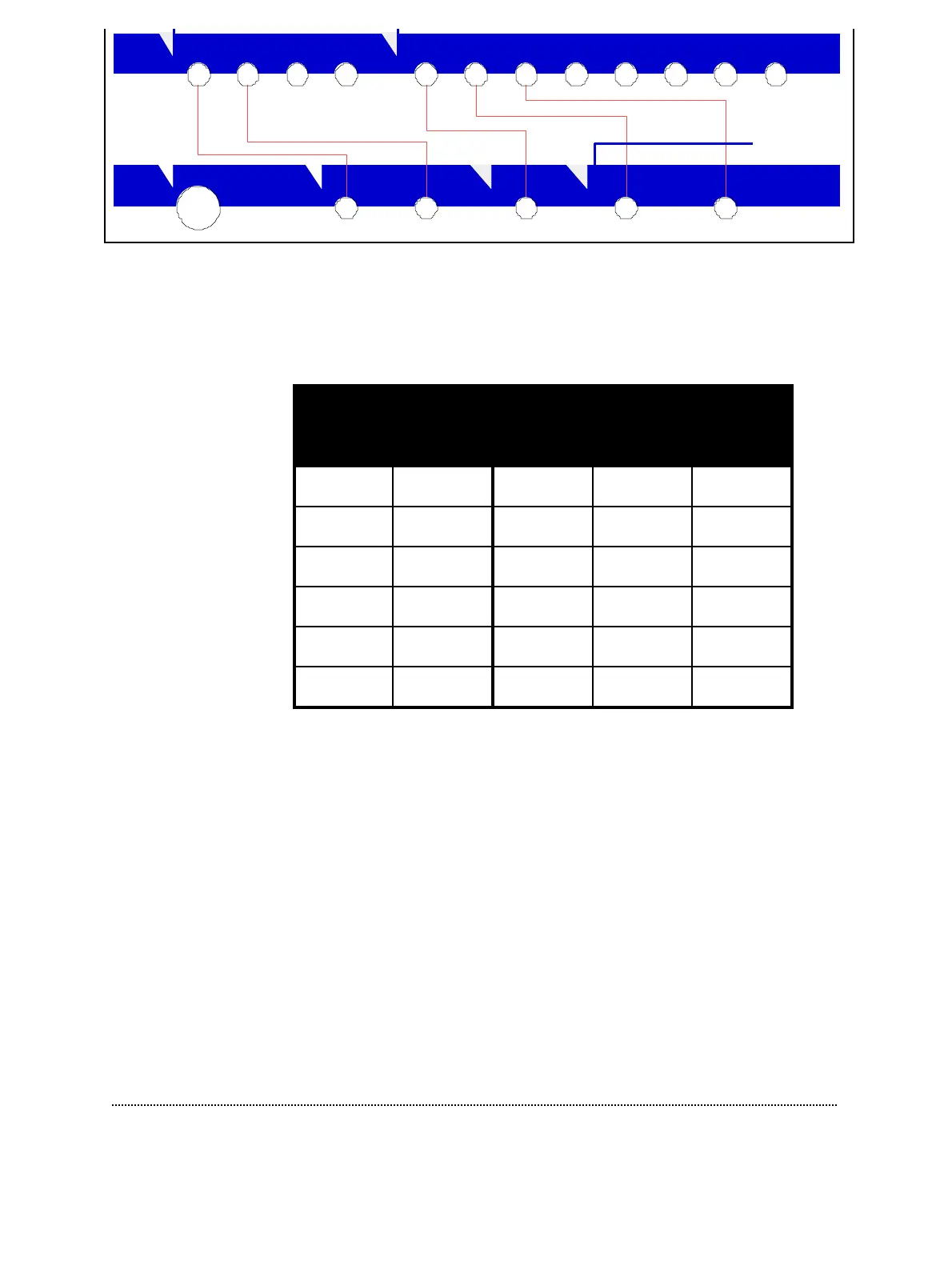
The following table shows you the combinations for the different amplifiers: EPC9,
EPC9 Double, and Triple. The EPC9 Triple has only one free AD input left (ADC-6),
the remaing channels are internally connected with the corresponding channels of
the amplifier. Therefore, only three connections (2 DA-channels and 1 AD-channel)
have to be made for the three amplifiers.
Amplifier Input Amplifier Output
Test Input External
Stim. Input
Voltage
Monitor
Filter 1 Filter 2
DAC 0 DAC 1 ADC 0 ADC 1 ADC 2
DAC 2 DAC 3 ADC 4 ADC 5 ADC 6
DAC 2 DAC 3 ADC 4 ADC 5 ADC 6
DAC 2 DAC 3 not tested not tested ADC 6
DAC 2 DAC 3 not tested not tested ADC 6
DAC 1 DAC 3 not tested not tested ADC 6
If the connection test fails, you will get an error message and the chance to repeat the
test an additional time. After the connection test you will have to remove all BNC
cables and connect a 10 MΩ resistor to the probe input. You can use the model circuit
and switch it into the “10 M” position. If the resistance is out of range (e.g. due to a
wrong position of the switch) you will see an error message and will be asked to
repeat the resistor test. After removing all BNC cables, you can proceed with the test.
It will continue for a while and you will get a final message reporting the status of
the amplifier, the probe and the connections. If any one of these fails you will see an
alert similar to the following one and get the chance to print out the error protocol.
0 0 11 22 3 3 54 6 7
PROBE
TEST
INPUT
EXTERNAL
STIM.INPUT
VOLTAGE
MONITOR
FILTER 1 FILTER 2
STIM1 STIM2 STIM3 TEST
IMON1 IMON2 IMON3 MUXVMON1 VMON2 VMON3
CURRENT MONITOR