Operating Modes EPC9 Manual 55
viewport now becomes an I-membrane display and may be used to inject a steady
command current through the action of the feedback amplifier. In E9Screen, the
membrane potential is shown in the I-mon display; in Pulse, the I-mon display is
converted to V-mon).
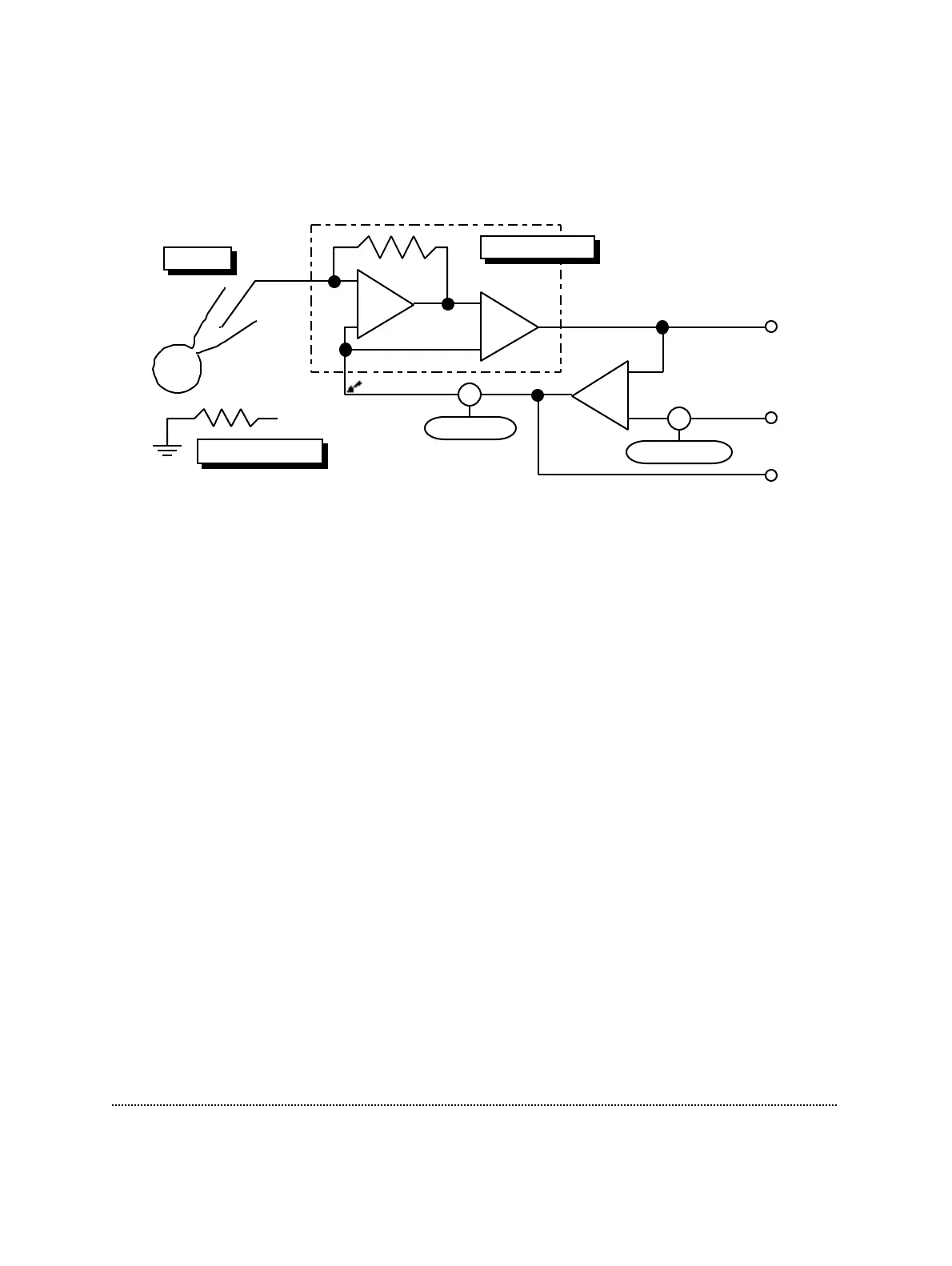
Ref. Pot.
V
0
-Offset
Σ
Pipette
Current
Monitor
Stim. In
Voltage
Monitor
Bath Electrode
IV Converter
Σ
I-membrane
You can use the Current Clamp mode to measure the resting potential or spontaneous
action potentials in a whole-cell recording, and the membrane potential will be
shown on the V-mon display. A commanded current can be injected while the pipette
potential is measured. The commanded current is determined by the sum of voltages
from the Stim. In signal and the I-membrane control.
Two current clamp scaling ranges can be selected: 1 and 10 pA/mV (with the
exception of the EPC9 versions “A” and “C” which have a fixed CC-scaling of 1
pA/mV). When the CC-scaling is set to 1 pA/mV, a command from the Pulse
Generator or from the I-membrane control that would give rise to 1 mV in the Voltage
Clamp mode instead gives rise to 1 pA in the Current Clamp mode. This relationship
of 1 and 10 pA/mV holds regardless of the Gain setting. The polarity is the usual
one, in which positive stimuli result in currents flowing out of the pipette.
Note: The “Gain” settings are restricted to the intermediate range, i.e. 0.5-20 mV/pA, in
current-clamp mode.
When switching from voltage-clamp to current-clamp mode, I-membrane will be set
to whatever is needed in order to keep the membrane voltage at the value that was
commanded in voltage clamp. Likewise, upon returning to voltage clamp, V-
membrane will be maintained. Thus, switching modes will be as gentle as possible,
since the membrane potential will always remain constant. If you wish to switch
modes under different conditions, it is convenient to program a macro to, for
example, set a holding current value immediately after switching to current clamp.
The EPC9 allows the functions of C-fast and R
s
-comp to be on when entering current-
clamp mode. C-fast then becomes a “negative capacitance” adjustment and R
s
-comp
becomes a “bridge” adjustment.