(3) Adjusting nut (4) Brake joint pin
(A) Cut-out not seated (B) Cut-out seated
3
44
3
(1) Arrow (2) Brake arm
(3) Reference mark (4) Brake panel
NOTE
If proper adjustment cannot be obtained by
this method, visit your Authorised Hero
MotoCorp workshop.
(e) Brake wear indicators
When the brake is applied, an arrow (1), fixed
to the brake arm (2), moves towards a
reference mark (3) on the brake panel (4). If
the arrow aligns with the reference mark on
full application of the brake, the brake shoes
must be replaced.
Front brake wear indication
42
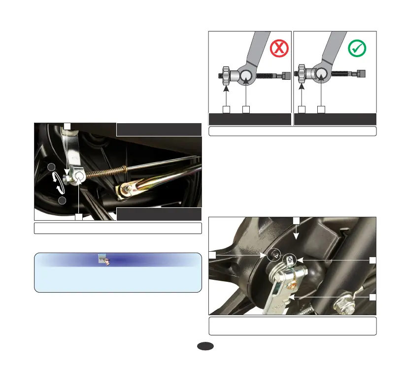
•
Measure the brake pedal (1) free play
before the brake starts to take hold.
Free play (2) should be 20-30 mm.
•
Make sure that the cut-out on the adjusting
nut is seated on the brake joint pin (4) after
the final adjustment has been made.
•
Apply the brake several times and check for
free wheel rotation when released.
•
If adjustment is necessary, turn the rear
brake adjusting nut (3).
CW- Clockwise, ACW- Anticlockwise
(3) Adjusting nut (4) Brake joint pin
3
4
A
B
(A) Decrease free play (CW)
(B) Increase free play (ACW)
2
1
4
3