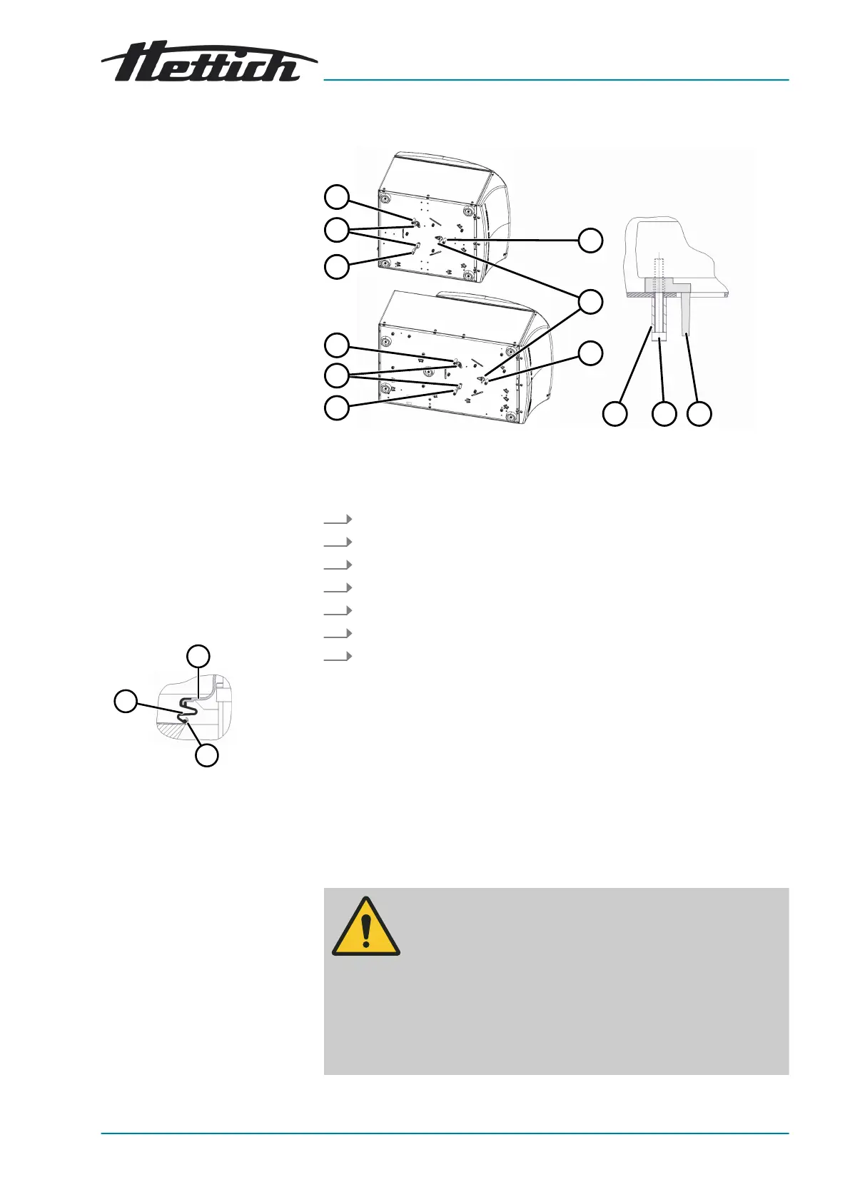
1 Motor cover
2 Edge of the centrifuging
chamber
3 Bellows
Setting up the centrifuge
Fig. 14: Transport lock
1 Transport lock
2 Screw
3 Spacer sleeve
1.
Lay the device down on its right-hand side.
2. Unscrew 3 screws (
2
) with 3 spacer sleeves (
3
).
3. Remove 3 transport locks (
1
).
4. Keep the screws, spacer sleeves and transport locks in a safe place.
5. Place the device upright.
6. Open the lid.
7. For UNIVERSAL 320 R:
Check the bellows (
3
) underneath the motor cover for correct
seating.
The bellows (
3
) must be placed over the edge of the motor cover (
1
)
and over the edge of the centrifuging chamber (
2
).
5.3
Setting up and connecting the centrifuge
WARNING
Risk of injury due to failing to maintain a
sufcient distance to
the centrifuge.
− As per EN/IEC 61010-2-020, no persons, hazardous
materials or objects may be present within a safety zone
of 300mm around the centrifuge during a centrifugation
run.
−
A distance of 300mm from the ventilation slots and ven-
tilation openings of the centrifuge must be maintained.
 Loading...