8 | Maintenance
34 / 49 Hidrostal AG
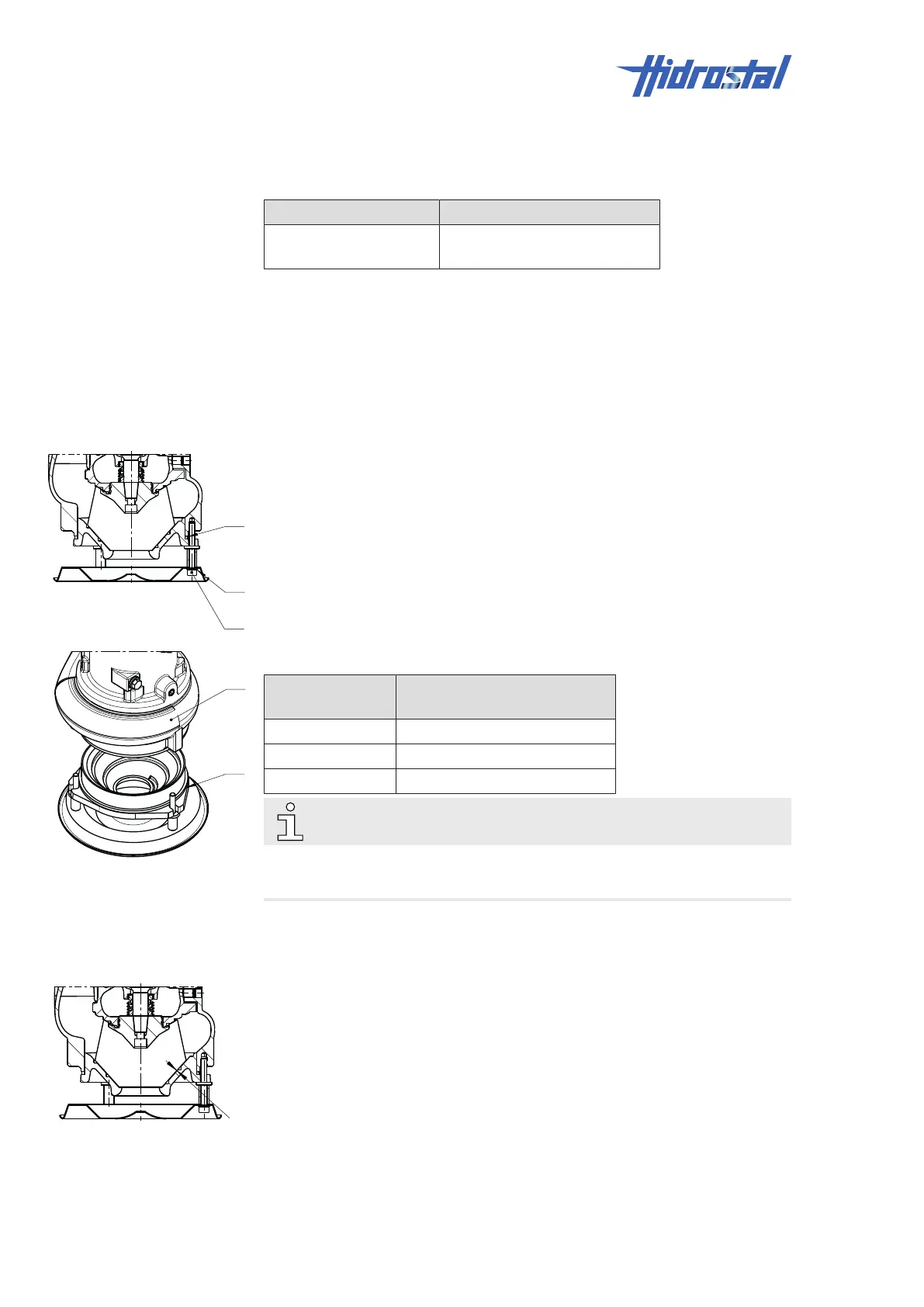
3. If the measured value exceeds the max. permissible value or the
impeller (1) grinds on the inlet cone (2), adjust the impeller clearance,
see Readjusting impeller clearance “C” [▶34].
Hydraulic size Max. impeller clearance “C”
A2Q, BN2, BE2, BN3,
BK3
0.3mm
8.4.3.4 Readjusting impeller clearance “C”
The impeller clearance is adjusted with rings of different thickness.
1. Make sure that impeller clearance “S” is within the permissible range,
see Checking impeller clearance “S” [▶33].
2. Make sure that the pump is positioned in a vertical position on a surface
and attach lifting gear on the drive unit to prevent it from tipping.
3. Remove all hexagon socket cheese-head screws (1) and spring rings
(2).
4. Lift drive unit and pump hydraulic housing (3) off the suction cover (4).
Pump type Available spacer rings,
thickness in mm
A2Q 0.5 / 1.0 / 2.0
BN2, BE2 0.5 / 3.0 / 4.0 / 5.0
BN3, BK3 0.5 / 3.0 / 4.0 / 5.0
NOTE
With every 0.5mm spacer ring thickness, the impeller clearance “C” is
increased by approximately 0.35mm.
5. Insert rings (5) until the impeller clearance corresponds to the
specification. See table in chapter Checking clearance “C” [▶33].
6. Reassemble the pump.
7. Check clearance “C” between impeller and inlet cone with a feeler gauge
after 0, ¼, ½, and ¾ revolutions of the impeller. See Checking
clearance “C” [▶33].
8. Adjust the thickness of the spacer rings if clearance “C” does not meet
the specification.