Chapter 9. External View
9-5
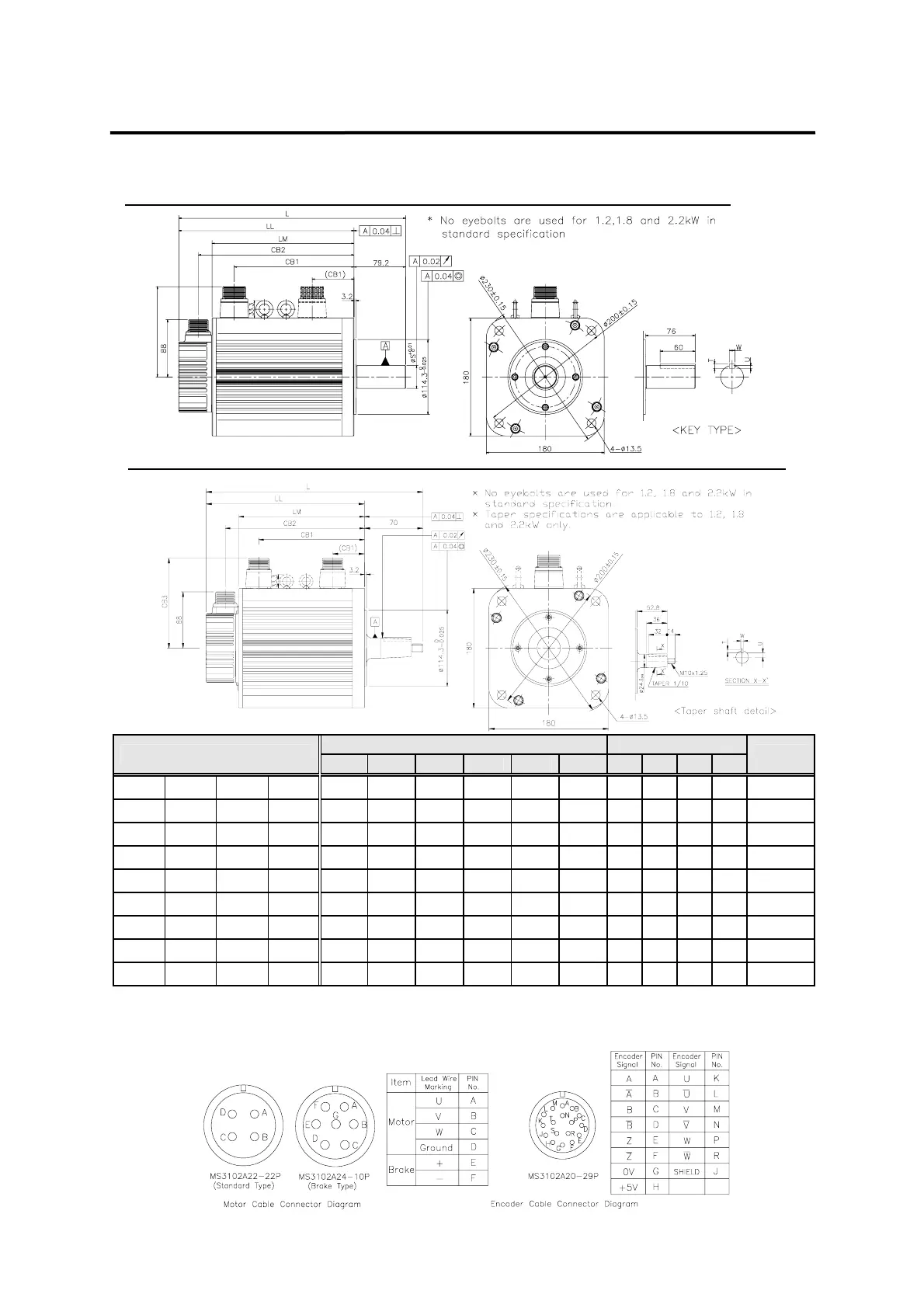
9.2.4 Flange 180 Series
External dimensions Key dimensions
Model
L LL LM CB1 CB2 CB3 S T U W
Weight
CN30A KN22A TN20 LN12A
265
(332)
186
(253)
135
(202)
102
(96)
156
(223)
138 35 5 3 5
12.9
(18.5)
KN35 TN30 LN20
300
(367)
221
(288)
170
(237)
137
(96)
191
(258)
138 35 8 5 10
18.2
(24.0)
CN50A
310
(377)
231
(298)
180
(247)
147
(96)
201
(268)
138 35 8 5 10
19.9
(25.7)
KN55 TN44 LN30
350
(417)
271
(338)
220
(287)
187
(96)
241
(308)
138 35 8 5 10
26.8
(32.5)
LN40
410
(477)
331
(398)
280
(347)
247
(96)
301
(368)
138 35 8 5 10
36.1
(41.8)
TN75
461
(527)
382
(448)
331
(397)
298
(96)
352
(418)
147 35 8 5 10
45.7
(51.4)
KF22 TF20 LF12
347
(421)
268
(342)
217
(291)
181
(96)
238
(312)
138 35 8 5 10
17.2
(24.7)
KF35 TF30 LF20
407
(476)
328
(397)
277
(346)
241
(96)
298
(367)
138 35 8 5 10
27.4
(34.9)
KF50 TF44 LF30
507
(571)
428
(492)
377
(441)
341
(96)
398
(462)
138 35 8 5 10
38.3
(45.8)
*) Figures in ( ) indicate brake-attached type. *) Use DC 90V for brake input power supply. *)In case of Taper shaft, shaft length is shorted
9.2mm.
Straight Shaft(Standard) Type (Dotted lines indicate position of brake-attached connectors)
CB3
Taper Shaft(Standard) Type (Dotted lines indicate position of brake-attached connectors)