SC2000 Series Vision Sensor User Manual
4
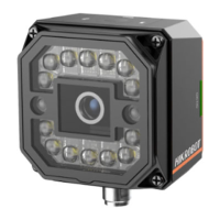
Chapter 3 17-Pin Interface
Read the following section to get definitions of 17-pin interface.
1
10
9
7
6
4
3
16
15
14
2
12
17
13
5
8
11
Figure 3-1 17-Pin Interface
Table 3-1 Pin Definitions
Direct current power supply positive
Can be configured as input or output
RS-232 serial port output
Fast Ethernet signal MDI0+
Fast Ethernet signal MDI1-
Can be configured as input or output
Direct current power supply negative
Can be configured as input or output
Fast Ethernet signal MDI0-
Fast Ethernet signal MDI1+
 Loading...