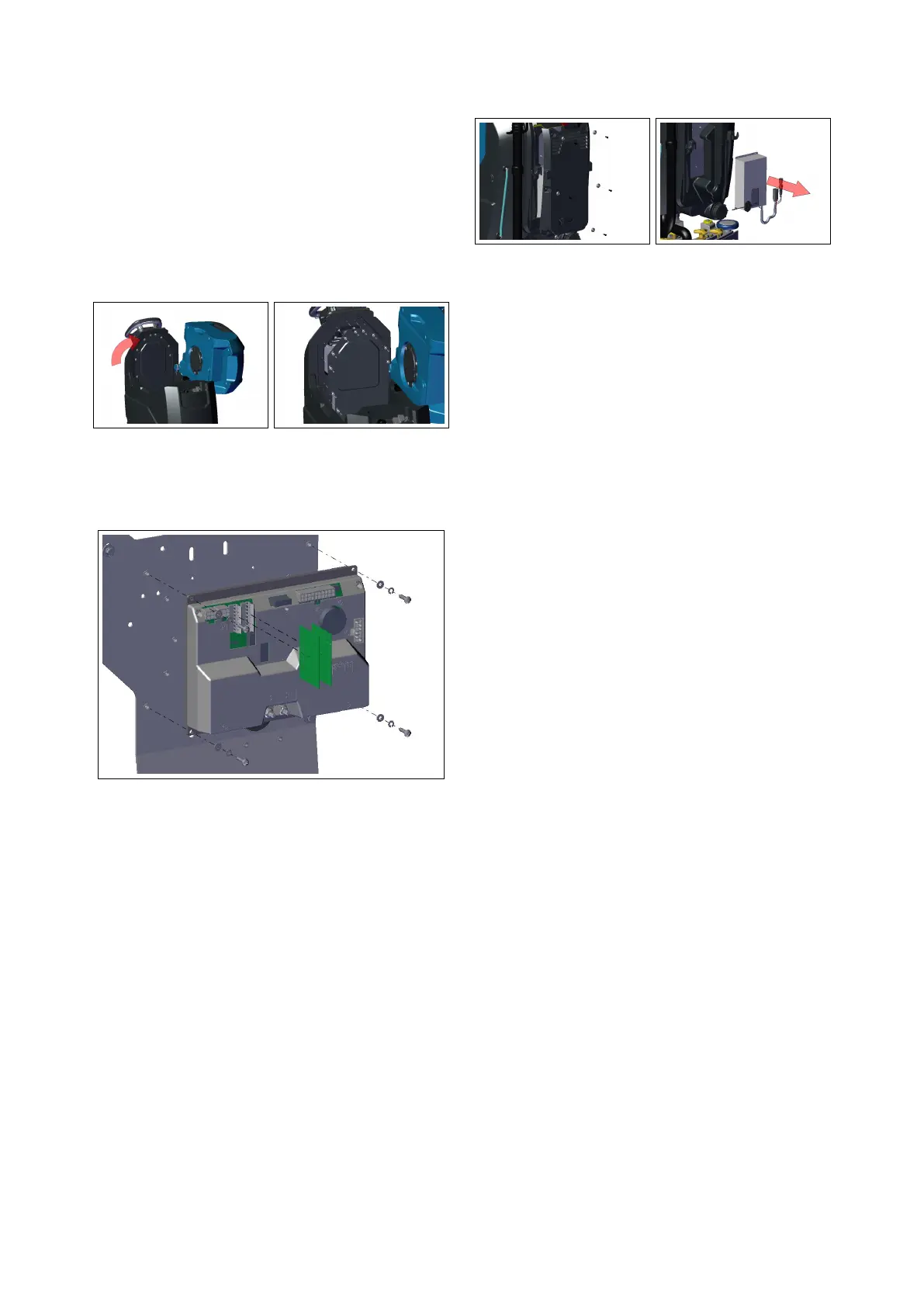
• Disconnect all the cables, remove
the 4 screws securing the board to
the panel and remove it.
• Disconnect the Actuator Board from
the connector of the Main Board.
4.1.2-6 4.1.2-7
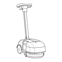
4.1.3 Battery Charger
• Put the machine in safe conditions.
• Remove the rear Carter by unscrew-
ing the fixing screws (see section 4.14.1.3-8
at page 22).
• Disconnect the charger cables from
the machine harness.
• Remove the screws securing the
charger to the panel and remove it
(see fig. 4.1.3-9).
• Proceed at reverse to refit the part.
4.1.3-8 4.1.3-9
4.2 Mechanical Friction
System
4.2.1 Brush Deck Assembly
T26SC PLUS
• Release the brushes, lower the
Brush Deck and switch Off the ma-
chine.
• Put the machine in safe conditions.
• Remove the Front carter by un-
screwing the fixing screws (see fig. 4.2.3-
10)
• Remove the fixing screws to the
brush deck lifting arms (see fig. 4.2.3-11)
• Disconnect the electrical connector
of the brush motors and of the
solenoid valve.
• Disconnect the water hose from the
solenoid valve.
4.2.2 Brush Coupling Flange
• Put the machine in safe conditions
and remove the brushes.
• Lower the knob in order to block the
flange.
• Unscrew the motor shaft from the
Flange with an allen key (see fig. 4.2.3-
12).
• Proceed at reverse to refit the part.
22
 Loading...