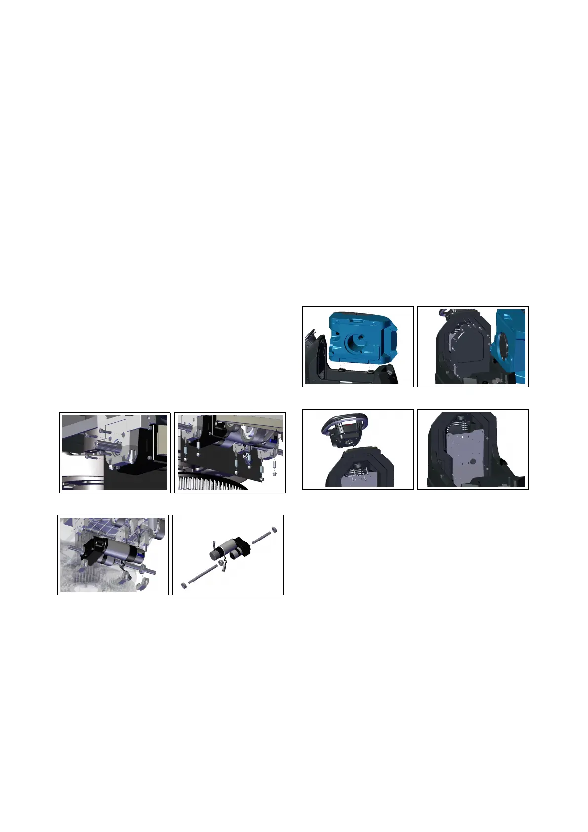
4.4.2 Traction Gearmotor
• Put the machine in safe conditions.
• Disassemble both wheels (see section
4.4.1 at page 25).
• Remove the 4 screws fixing the gear-
motor to the frame and bearing sup-
port (see fig. 4.4.2-23).
• Unplug the Electrical connector of
the Traction Gearmotor.
• Remove the fixing screws of the
bearing supports paying attention to
the gearmotor which will be free to
fall off to the ground (see fig. 4.4.2-24) (see
fig. 4.4.2-25).
• Remove the drive shafts and remove
the bearings (see fig. 4.4.2-26).
• Proceed at reverse to refit the part.
4.4.2-23 4.4.2-24
4.4.2-25 4.4.2-26
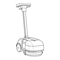
4.5 Solution Delivery Sys-
tem
4.5.1 Solution Tank
• Put the machine in safe conditions.
• Remove the recovery tank (see section
4.3.5 at page 24) (see fig. 4.5.1-27) and the elec-
tric system carter (see fig. 4.5.1-28).
• Remove the handlebar and the elec-
trical system panel (see fig. 4.5.1-29) (see fig.
4.5.1-30).
4.5.1-27 4.5.1-28
4.5.1-29 4.5.1-30
• Remove the rear carters (see fig. 4.5.1-31).
• Remove the lower and front screws
that secure the tank to the frame (see
fig. 4.5.1-32) (see fig. 4.5.1-33).
• Remove the lower carters and the
water assembly (see fig. 4.5.1-34).
• Remove the remaining parts (see fig.
4.5.1-35).
• Proceed at reverse to refit the part.
26
 Loading...